A gel pen for refilling ink
A gel pen and pen tip technology, used in ballpoint pens, printing, writing utensils, etc., can solve the problems of stuck, expensive, and can not work normally, and achieve the effect of increasing ink storage space, easy to carry, and comfortable to write.
- Summary
- Abstract
- Description
- Claims
- Application Information
AI Technical Summary
Problems solved by technology
Method used
Image
Examples
Embodiment 1
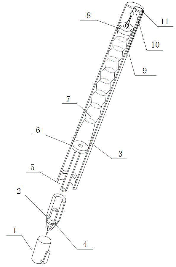
[0021] Such as figure 1 The shown gel pen for refilling ink includes a pen case 3, a pen head 2, and a pen cap 1. The pen head 2 is connected to the pen case 3, and the pen cap 1 is installed on the pen head 2. It is characterized in that: it also includes a The nib 4 in the 2 is connected successively and installed in the sealed ink tray 6, the ink reservoir 7, the ink pumping device in the pen housing 3, and the connecting rod 5 connecting the nib 4 and the ink reservoir.
[0022] The sealed ink tray 6 is located at the lower end of the ink reservoir 7, and the ink reservoir 7 communicates with the connecting rod 5 at the lower part through the round hole in the middle of the sealed ink tray 6. During use, the ink in the ink reservoir 7 flows into the nib located at the lower nib through the connecting rod, and then flows out from the nib by hydraulic action. The nib 4 is embedded in the nib 2, and the rear end of the nib 4 is set as a cylindrical hollow rod, which is match...
Embodiment 2
[0024] As an optimized embodiment of Embodiment 1, the ink reservoir 7 is a compressed ink reservoir with a soft plastic folded structure. This structure can effectively ensure that the pen can work normally many times when it is watered and ink drawn. The hard ink tube of the existing pen core is replaced by a compressed ink storage device, and the ink storage device made of soft plastic with a structure similar to the folded part of the straw is used to complete the ink filling and discharging process through the change of the ink storage volume in it. , to achieve the flow balance of the ink in the tube.
[0025] The ink pumping device includes a one-way limit valve 8 connected to the ink reservoir 7 at one end and an ink pumping control line 9 connected to the other end of the one-way limit valve 8. One end has an outlet hole 10, and the other end of the ink pumping control line 9 passes through the outlet hole 10 of the pen case.
[0026] The outlet hole 10 is arranged ...
Embodiment 3
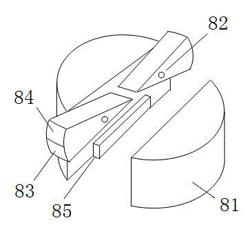
[0029] Such as figure 2 As shown in , as a further optimization of Embodiment 2, the one-way limit valve 8 includes a valve body 81 and a limit block 82 installed on the valve body 81. One half of the arc-shaped end face of the limit block is set as a smooth surface 83, and the other half is set as a rough surface 84. The smooth surface 83 faces the direction of the nib, and the rough surface 84 faces away from the direction of the nib. In this way, during normal writing, due to the negative pressure, the single The limit valve 8 only moves towards the direction of the nib, and squeezes the compression type ink reservoir to discharge ink.
[0030] As the ink gradually decreases during the writing process, the compressed ink reservoir 7 tends to move downward under the action of gravity, and the smooth surface of the arc-shaped end surface contacts the pen shell under the action of friction, so the entire ink pumping device can be normal. When the pen tip moves in the opposit...
PUM
 Abstract
Description
Claims
Application Information
 - R&D
- Intellectual Property
- Life Sciences
- Materials
- Tech Scout
- Unparalleled Data Quality
- Higher Quality Content
- 60% Fewer Hallucinations
Browse by: Latest US Patents, China's latest patents, Technical Efficacy Thesaurus, Application Domain, Technology Topic, Popular Technical Reports.
© 2025 PatSnap. All rights reserved.Legal|Privacy policy|Modern Slavery Act Transparency Statement|Sitemap|About US| Contact US: help@patsnap.com


