Forward and reverse speed adjustable handle for electric vehicle and power control device for electric vehicle
An electric vehicle, forward and reverse technology, applied in the direction of bicycle control system, bicycle accessories, transportation and packaging, etc., can solve problems such as difficult promotion and use
- Summary
- Abstract
- Description
- Claims
- Application Information
AI Technical Summary
Problems solved by technology
Method used
Image
Examples
Embodiment 1
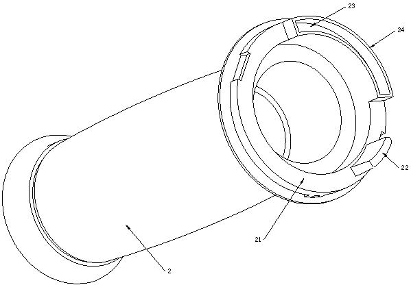
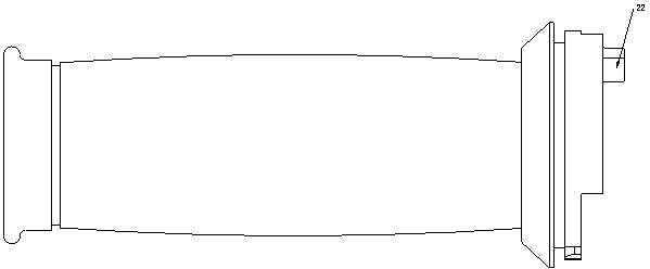
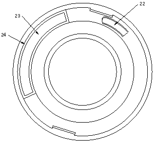
[0061] see Figure 4-8 The forward and reverse speed-regulating handlebar for the electric vehicle shown includes a fixed piece consisting of a handlebar 100 and a handle base 1 fixed on the handlebar 100, and rotates the handle 2 arranged on the handlebar. See Figure 1-3 A boss 22 and an arc-shaped body 24 with an arc-shaped groove 23 are provided on the handle end face 21 axially opposite to the handle seat. The arc-shaped groove is used to place arc-shaped magnetic steel (arc-shaped permanent magnet) 3 . The arc center angle B of the arc permanent magnet is about 100°.
[0062] see Figure 7 , 8 , There is an annular groove 11 on the handle seat opposite to the axial direction of the handle. The axis of the ring groove 11, the axis of the handle, the axis of the handle rod, and the axis of the arc magnetic steel are all coaxial. The bottom surface of the ring groove 11 is provided with a positive limit block 12 , an arc-shaped spring seat 13 , and a Hall sensor 4 .
...
Embodiment 2
[0070] Embodiment 2 is different from Embodiment 1 in that: when the arc-shaped permanent magnet rotates to different positions relative to the Hall sensor, the output signal of the Hall sensor is a pulse width modulation signal with a duty ratio of 5%-95%. In the reset position, the duty cycle of the hall sensor output signal (reference signal) is about 50%.
[0071] When the electric vehicle needs to move forward, apply counterclockwise torque to the handle and turn the handle counterclockwise. As the angle of rotation of the handle (relative to the reset position) increases, the duty cycle of the output signal of the Hall sensor will change from 50% to 50%. Gradually increase. Until the arc-shaped body 24 contacts the positive limit block 12 in the circumferential direction and the handle cannot continue to rotate counterclockwise, the duty cycle of the output signal of the Hall sensor reaches a maximum of 95%. The controller controls the motor to output a larger torque ac...
Embodiment 3
[0074] see Figure 9 (and refer to Figure 5 , 6 ), the difference between embodiment 3 and embodiment 1 is that there is no reverse limit card 14 in embodiment 1 on the outer wall 15 of the ring groove in embodiment 3, and the handle 2 and slider 5 in embodiment 3 One-piece structure (the slider can be regarded as a part of the handle 2). The turning handle is in the reset position under the joint action of the left turning spring and the right turning spring. When the handle is turned, the handle (and slider) turn together.
PUM
 Abstract
Description
Claims
Application Information
 - R&D
- Intellectual Property
- Life Sciences
- Materials
- Tech Scout
- Unparalleled Data Quality
- Higher Quality Content
- 60% Fewer Hallucinations
Browse by: Latest US Patents, China's latest patents, Technical Efficacy Thesaurus, Application Domain, Technology Topic, Popular Technical Reports.
© 2025 PatSnap. All rights reserved.Legal|Privacy policy|Modern Slavery Act Transparency Statement|Sitemap|About US| Contact US: help@patsnap.com


