Leakproof dynamic pressure type valve plate

A valve plate, dynamic pressure type technology, applied in the field of hydraulic components, can solve the problems of large overturning moment of the cylinder and large leakage, and achieve the effects of reducing friction and wear, reducing leakage and improving volumetric efficiency

Inactive Publication Date: 2014-09-03
LIUZHOU LIUGONG HYDRAULIC COMPONENTS +1
View PDF6 Cites 11 Cited by
  • Summary
  • Abstract
  • Description
  • Claims
  • Application Information

AI Technical Summary

Problems solved by technology

[0004] The purpose of the present invention is to provide a leak-proof dynamic pressure distribution plate, which can solve the problems of large

Method used


Image

  • Leakproof dynamic pressure type valve plate
  • Leakproof dynamic pressure type valve plate
  • Leakproof dynamic pressure type valve plate

Examples


Example Embodiment

[0023] Example 1

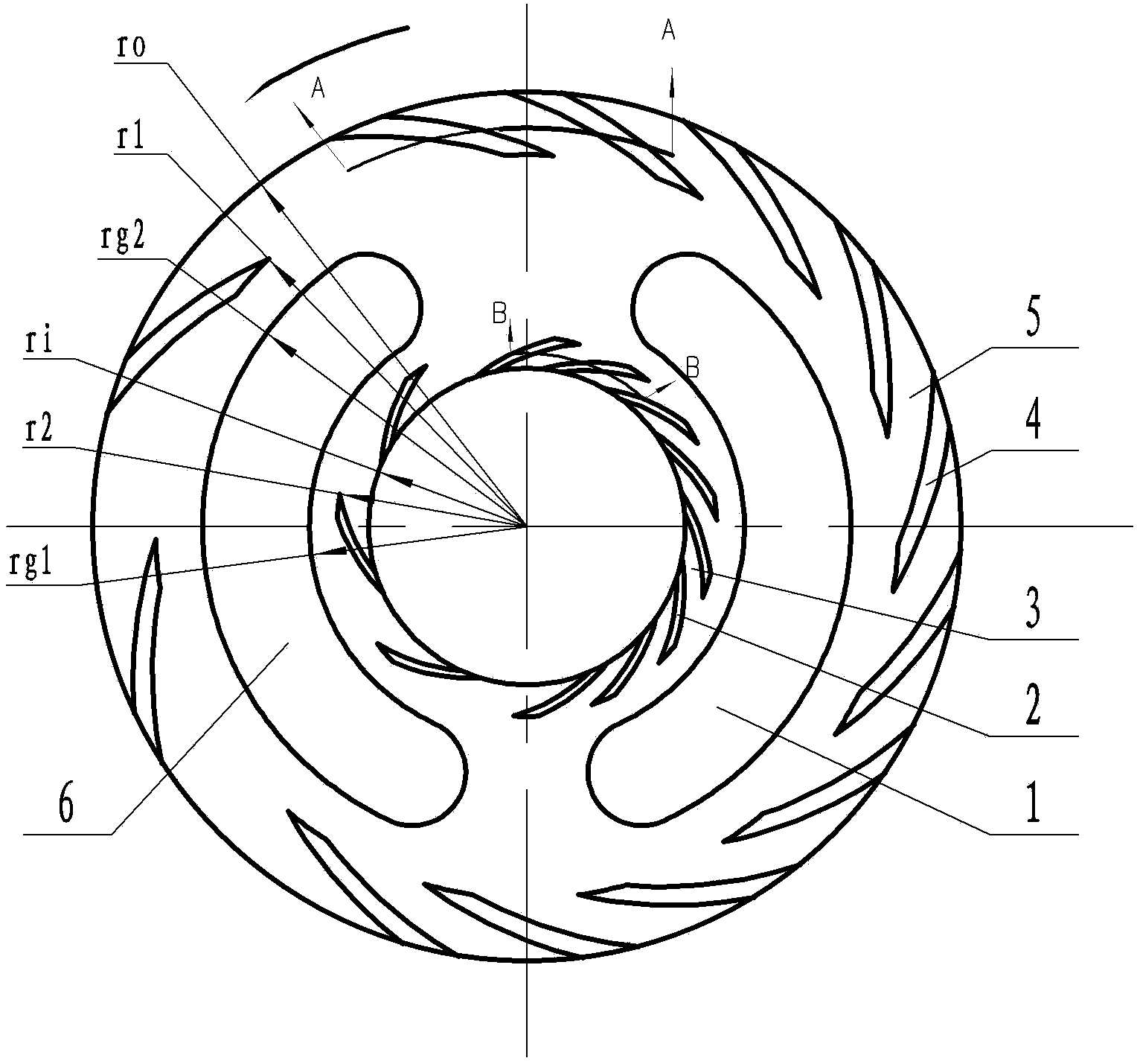
[0024] figure 1 The anti-leakage dynamic pressure distribution plate shown includes a distribution plate body with a waist-shaped distribution window, and the waist-shaped distribution window includes an oil suction port 1 in a low oil pressure area of ​​the valve body body and an oil pressure port 6 in a high oil pressure area ; On the sealing end face of the distribution plate body, a plurality of curved first miniature grooves 2 are arranged along the inner ring surface of the inner side of the oil suction port 1 and the inner side of the oil pressure port 6, and along the outer side of the oil suction port 1 and the outer side of the oil pressure port 6 The outer ring surface is provided with a plurality of curved second micro-channels 4; the first micro-channels 2 and the second micro-channels 4 are arc grooves with one end closed and the other end open, and the first micro-channels 2 are closed. The end extends to the inner edge of the distribution pl...

Example Embodiment

[0026] Example 2

[0027]The first micro-channel and the second micro-channel of the anti-leakage dynamic pressure distribution plate of this embodiment are both spiral grooves, and the number of the first micro-channel is 5 on the side of the oil pressure port, and the groove depth is 3 microns. The number of grooves on the side of the oil suction port is 9, the groove depth is 5 microns, the ratio of the total cross-sectional area of ​​the first micro channel to the total area of ​​the first sealing weir is 0.4:1, and the radius ri of the inner edge of the valve plate body is 20 mm, the closed ends of all the first micro channels are on the same circle, the radius r2 of this circle is 23.5 mm, the radius rg1 inside the oil pressure port is 27 mm, and the inner edge of the valve plate body reaches the first The ratio of the radial distance of the closed end of the micro-channel to the radial distance inside the oil pressure port is (r2-ri): (rg1-ri)=(23.5-20): (27-20)=0.5:1 ...

Example Embodiment

[0028] Example 3

[0029] The first micro-channel and the second micro-channel of the anti-leakage dynamic pressure distribution plate of this embodiment are both spiral grooves, and the number of the first micro-channel is 55 on the side of the oil pressure port, and the groove depth is 2 microns. The number of grooves on the side of the oil suction port is 45, the groove depth is 1 micron, the ratio of the total cross-sectional area of ​​the first micro channel to the total area of ​​the first sealing weir is 10:1, and the radius ri of the inner edge of the valve plate body is 20 mm, the closed ends of all the first micro channels are on the same circle, the radius r2 of this circle is 22 mm, the radius rg1 inside the oil pressure port is 40 mm, and the inner edge of the valve plate body reaches the first The ratio of the radial distance of the closed end of the micro channel to the radial distance inside the oil pressure port is (r2-ri): (rg1-ri)=(22-20): (40-20)=0.1:1 ; T...


PUM

PropertyMeasurementUnit
Groove depthaaaaaaaaaa

Abstract

The invention discloses a leakproof dynamic pressure type valve plate, and relates to the technical field of engineering machines. The leakproof dynamic pressure type valve plate comprises a valve plate body with an oil suction opening and an oil pressing opening, a plurality of bending first micro type channels are arranged on the sealed end face of the valve plate body along the inner ring face of the inner side of the oil suction opening and the inner ring face of the inner side of the oil pressing opening, and a plurality of bending second micro type channels are arranged on the sealed end face of the valve plate body along the outer ring face of the outer side of the oil suction opening and the outer ring face of the outer side of the oil pressing opening. One ends of the first micro type channels are sealed, and the sealed ends extend towards the inner edge of the valve plate body to form openings. One ends of the second micro type channels are sealed, and the sealed ends extend towards the outer edge of the valve plate body to form openings. The rotating direction of the second micro type channels is the same as the counterrotating direction of the valve plate body, and the rotating direction of the first micro type channels is opposite to that of the second micro type channels. According to the valve plate, the problems that the amount of leakage between an existing dynamic pressure type valve plate and a plunger pump cylinder body is large, and the overturning moment of the cylinder body is large are solved, the volume efficiency of the valve plate is improved, and the service life is prolonged.

Description

technical field [0001] The invention relates to the technical field of hydraulic components, in particular to a fluid dynamic sealing valve plate for a plunger pump or a motor. Background technique [0002] The leakage of the plunger pump or motor has become a bottleneck restricting its pressure and efficiency improvement, and the leakage of the valve gap is the most important part of the piston pump or motor. How to reduce the leakage of the valve gap has become an important part of the current research. topic. In the existing technical field, in order to improve the service life and work reliability of the plunger pump or motor and reduce power loss, auxiliary supports are usually used for some plunger mechanical distribution pairs, including static pressure supports and dynamic pressure supports. And other measures to reduce the friction and wear of the distribution pair, however, the static pressure support and the dynamic pressure support did not reduce its leakage, an...

Claims


Application Information

Patent Timeline
IPC IPC(8): F04B53/00
Inventor 刘彤蒋拓祝晓丽高名乾唐晓阳肖华丁卫李瑞生
Owner LIUZHOU LIUGONG HYDRAULIC COMPONENTS
Why Eureka
Try Eureka