Labor-saving rotary power transmission device

A technology of transmission device and rotating power, applied in the direction of transmission device, gear transmission device, belt/chain/gear, etc., can solve the problems of reducing efficiency, wasting work and time, etc., and achieve the effect of reducing operating costs and saving power energy

Inactive Publication Date: 2014-09-03
宁湘均
View PDF6 Cites 1 Cited by
  • Summary
  • Abstract
  • Description
  • Claims
  • Application Information

AI Technical Summary

Problems solved by technology

However, the repeated use of the lever will waste work and time and reduce the efficiency. The movable pulley cannot change the direction of the force, so the independent use is greatly restricted in the mechanical force transmission and it is difficult to achieve the desired effect.

Method used


Image

  • Labor-saving rotary power transmission device
  • Labor-saving rotary power transmission device
  • Labor-saving rotary power transmission device

Examples


Embodiment 1

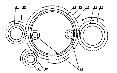
[0028] Such as figure 1 As shown, the power end gear 11, the load end gear 31 and the fulcrum gear 41 are directly meshed with the lever gear 21 respectively. An arc is formed, and the fulcrum gear 41 is located in the interval of the arc. In this example, the power end gear 11, the load end gear 31 and the fulcrum gear 41 all rotate counterclockwise, and the lever gear 21 rotates clockwise. The arc is located at figure 1 The lower peripheral area of ​​the middle lever gear 21; the lever gear 21 is provided with external teeth 22 and a central through hole (not marked in the figure), the inner wall circumference of the lever gear 21 is provided with an annular groove 23, and the circumferential edge of the lever positioning wheel 24 is placed The positioning connection is realized in the annular groove 23 , and the power end gear 11 and the load end gear 31 are installed outside the lever gear 21 .

Embodiment 2

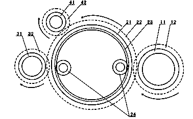
[0030] Such as figure 1 As shown, the power end gear 11, the load end gear 31 and the fulcrum gear 41 are directly meshed with the lever gear 21 respectively. An arc is formed, and the fulcrum gear 41 is located in the interval of the arc. In this example, the power end gear 11, the load end gear 31 and the fulcrum gear 41 all rotate clockwise, and the lever gear 21 rotates counterclockwise. The arc is located at figure 2 The upper peripheral area of ​​the middle lever gear 21; the lever gear 21 is provided with external teeth 22 and a central through hole (not marked in the figure), the inner wall circumference of the lever gear 21 is provided with an annular groove 23, and the circumferential edge of the lever positioning wheel 24 is placed The positioning connection is realized in the annular groove 23 , and the power end gear 11 and the load end gear 31 are installed outside the lever gear 21 .

[0031] combine figure 1 with figure 2 , in the above-mentioned embodiment ...

Embodiment 3

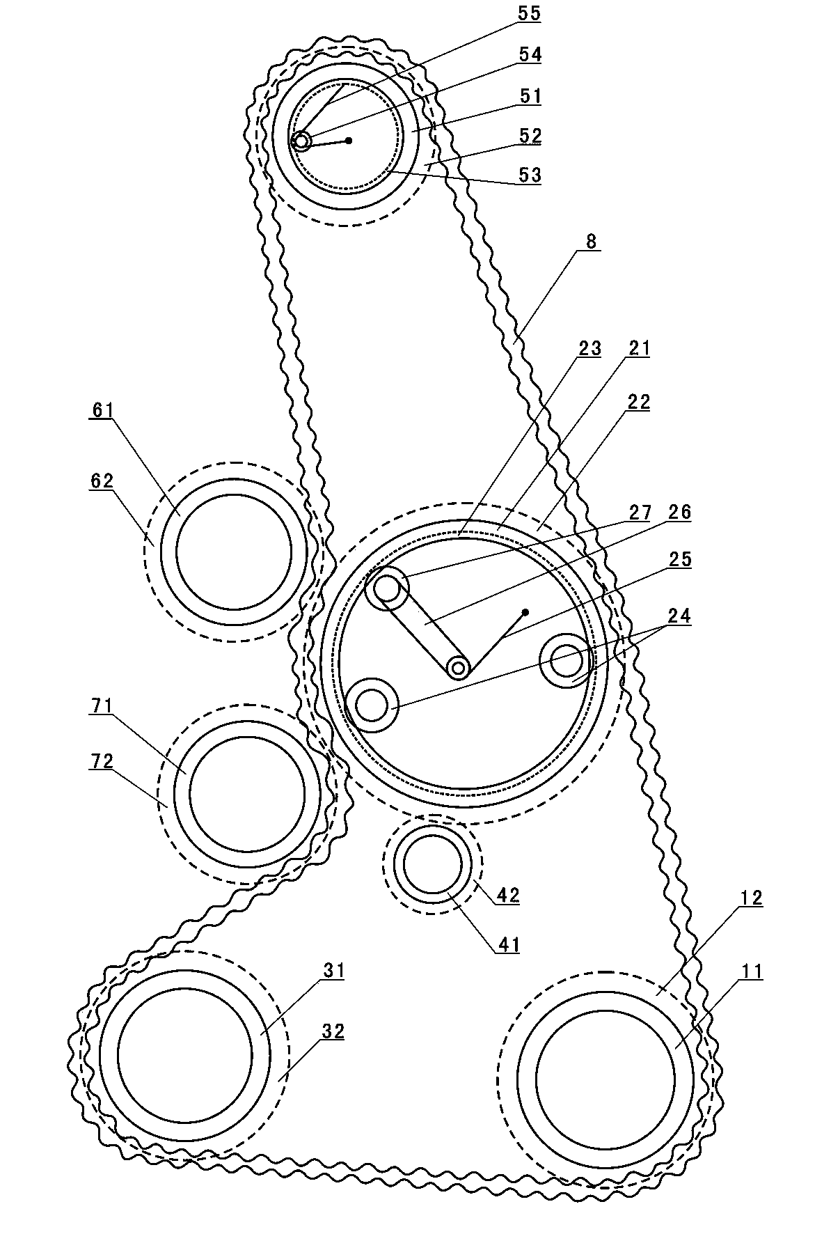
[0036] Such as image 3 As shown, the power end gear 11, the lever gear 21, the transition gear 51 and the load end gear 31 are meshed and connected by a chain 8, and the power end gear 11, the transition gear 51 and the load end gear 31 are located outside the lever gear 21 respectively. The bead gears 61 and 72 are installed outside the lever gear 21 and close to the bead gear 21. The bead gears 61 and 72 make the chain 8 mesh with the power end gear 11, the lever gear 21, the transition gear 51, and the load end gear 31 respectively. transmission; the lever gear 21 is provided with external teeth 22 and a central through hole, and the inner wall circumference of the lever gear 21 is provided with an annular groove 23, and a mobile support arm 26 is also installed in the central through hole of the lever gear 21, and the first part of the mobile support arm 26 One end is installed in the position close to the central point in the lever gear 21, and the second end of the mobi...


PUM


Abstract

The invention discloses a labor-saving rotary power transmission device. The labor-saving rotary power transmission device comprises a power end gear, a load end gear, a lever gear, a support point gear and a lever positioning wheel, wherein the power end gear, the load end gear and the support point gear are connected with the lever gear in a rotary transmission mode, the support point gear is located between the power end gear and the load end gear and is closer to the load end gear, the lever positioning wheel can rotate but can not move, and the lever positioning wheel is connected with the lever gear in a positioning mode so that the lever gear can rotate in a positioning mode. On the basis of direct transmission of a traditional gear, the lever gear, the support point gear and the lever positioning gear are additionally provided, three mechanics principles of a lever, a fixed pulley and a movable pulley are integrated, labor-saving transmission of rotary power is achieved, and the power transmission direction can be changed through simple processing according to needs. The labor-saving rotary power transmission device can be widely applied to rotary power transmission of various machines, meets the requirement for load acting, saves power energy, lowers operation cost, and is favorable for environment protection.

Description

technical field [0001] The invention relates to a power transmission device, in particular to a rotary power labor-saving transmission device. [0002] Background technique [0003] Most of the mechanical power is rotational power, especially the motor as the main power equipment, so most of the mechanical force transmission is the transmission of rotational power. The traditional rotary power transmission is mainly realized by one or more of the transmission shaft, speed changer, gear and chain, etc. The power in the transmission process is consistent, and the effect of labor saving cannot be achieved. Therefore, in order to increase the load power, the motor must be increased. Power means more energy consumption and more waste of resources, which not only fails to save costs, but also is not conducive to environmental protection. [0004] As we all know, both the lever and the movable pulley have the advantage of saving labor. The former increases the length of the mome...

Claims


Application Information

Patent Timeline
IPC IPC(8): F16H1/22F16H37/06
CPCF16H37/06
Inventor 宁湘均
Owner 宁湘均
Why Eureka
Try Eureka