Heat exchanger tube box welding structure and manufacturing method

A technology for welding structures and heat exchanger tubes, which is applied in the direction of heat exchanger shells, heat exchange equipment, lighting and heating equipment, etc., and can solve the difficulties of splicing welding seam blanking and welding of baffle plates and oval heads, Solve problems such as weld failure, achieve the effect of improving processing capacity and heat exchange efficiency, simplifying operation, and reducing costs

Inactive Publication Date: 2014-09-03
JIANGSU JIATAI EVAPORATION CRYSTALLIZATION EQUIP
View PDF0 Cites 2 Cited by
  • Summary
  • Abstract
  • Description
  • Claims
  • Application Information

AI Technical Summary

Problems solved by technology

[0003] Since the applicant introduced technical means such as forced circulation and continuous discharge into the evaporator crystallization equipment, which solved technical problems such as scaling and clogging, higher requirements were put forward for the treatment concentration and treatment efficiency of the heat exchanger. If the form of the elliptical head

Method used


Image

  • Heat exchanger tube box welding structure and manufacturing method
  • Heat exchanger tube box welding structure and manufacturing method
  • Heat exchanger tube box welding structure and manufacturing method

Examples


Embodiment

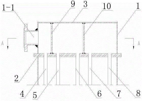
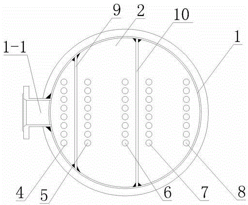
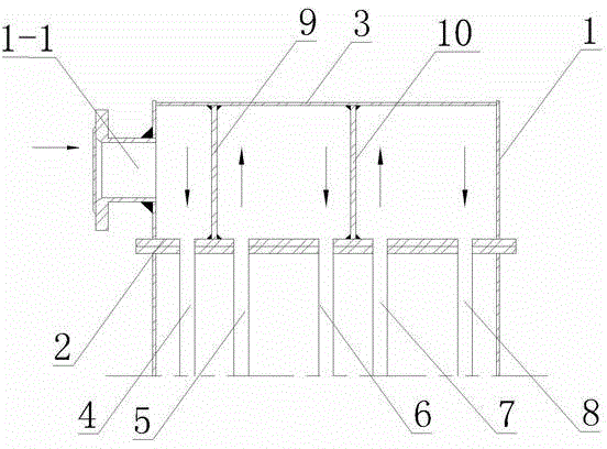
[0019] Embodiment: The welded structure of the heat exchanger tube box of this embodiment is as follows figure 1 and figure 2 As shown, it includes a vertical cylindrical cylinder 1, on the side wall of the cylinder 1, there is a feed port 1-1 for inputting the material to be processed, and a flat-bottomed head 3 is also welded on the top of the cylinder 1, A tube plate 2 is welded at the bottom of the cylinder body 1, and the bottom of the tube plate 2 is connected with the first heating tube 4, the second heating tube 5, the third heating tube 6, the fourth heating tube 7 and the fifth heating tube Tube 8 is connected. In order to facilitate segmental manufacturing and splicing installation, the edge of the tube plate 2 extends to the outside of the cylinder 1 and forms a flange.

[0020] There are vertical rectangular first baffles 8 and second baffles 9 welded inside the cylinder 1, the sides of which are connected to the vertical inner wall of the cylinder 1, and the t...


PUM


Abstract

The invention discloses a heat exchanger tube box welding structure and a manufacturing method. The structure comprises a barrel, wherein one side wall of the barrel is provided with a feed inlet, a flat base end socket and a tube plate are welded to the two ends of the barrel respectively, the lower portion of the tube plate is communicated with five heating tubes, two baffle plates in the barrel divides the barrel into three chambers, the first chamber enables the feed inlet to be communicate with the first heating tube, the second chamber enables the second heating tube to be communicated with the third heating tube, and the third chamber enables the fourth heating tube to be communicated with the fifth heating tube. The manufacturing method includes the steps of welding the barrel, the tube plate, the baffle plates and the flat base end socket in sequence. The heat exchanger tube box welding structure and the manufacturing method facilitate shaping of a tube box, enable welding operation to be more convenient, and better facilitate spacing distribution after baffling is completed.

Description

technical field [0001] The invention relates to a component of evaporation crystallization equipment and a manufacturing method, in particular to a heat exchanger pipe box welding structure and a manufacturing method. Background technique [0002] The working pressure of the heat exchanger is about 0.3Mpa, and the medium flowing inside is usually highly corrosive saline sewage. The conventional design in the chemical industry is to adopt the structure of a barrel-shaped container, and its end is made of a stamped oval head. It is because of the strong pressure resistance of the elliptical head, and the joint between the head and the cylinder is also convenient to adopt the flat welding method on the rolling frame. [0003] Since the applicant introduced technical means such as forced circulation and continuous discharge into the evaporator crystallization equipment, which solved technical problems such as scaling and clogging, higher requirements were put forward for the tre...

Claims


Application Information

Patent Timeline
IPC IPC(8): F28F9/18
Inventor 树晓荣
Owner JIANGSU JIATAI EVAPORATION CRYSTALLIZATION EQUIP
Why Eureka
Try Eureka