
Direct force and aerodynamic force composite control method and forward-direction interception guidance method

A composite control and aerodynamic technology, applied in the direction of offensive equipment, weapon types, projectiles, etc., can solve the problem that the dynamics and characteristics of the direct force and aerodynamic composite control system cannot be easily and truly reflected, and the control distribution does not consider the projectile. dynamic issues

Inactive Publication Date: 2014-09-03
NAVAL AERONAUTICAL & ASTRONAUTICAL UNIV PLA
View PDF5 Cites 14 Cited by
  • Summary
  • Abstract
  • Description
  • Claims
  • Application Information

AI Technical Summary

Problems solved by technology

[0005] The purpose of the embodiments of the present invention is to provide a direct force aerodynamic compound control method and a forward intercept guidance method considering the dynamics of the direct force aerodynamic compound control system, aiming at avoiding the complicated control required by the existing direct force aerodynamic compound control method The allocation problem and the solution to the existing forward pursuit and interception guidance law cannot be conveniently and realistically Reflect the dynamics and characteristics of the direct force and aerodynamic compound control system

Method used


Image

  • Direct force and aerodynamic force composite control method and forward-direction interception guidance method
  • Direct force and aerodynamic force composite control method and forward-direction interception guidance method
  • Direct force and aerodynamic force composite control method and forward-direction interception guidance method

Examples


Embodiment Construction

[0166] In order to make the object, technical solution and advantages of the present invention more clear, the present invention will be further described in detail below in conjunction with the examples. It should be understood that the specific embodiments described here are only used to explain the present invention, not to limit the present invention.

[0167] The application principle of the present invention will be further described below in conjunction with the accompanying drawings and specific embodiments.

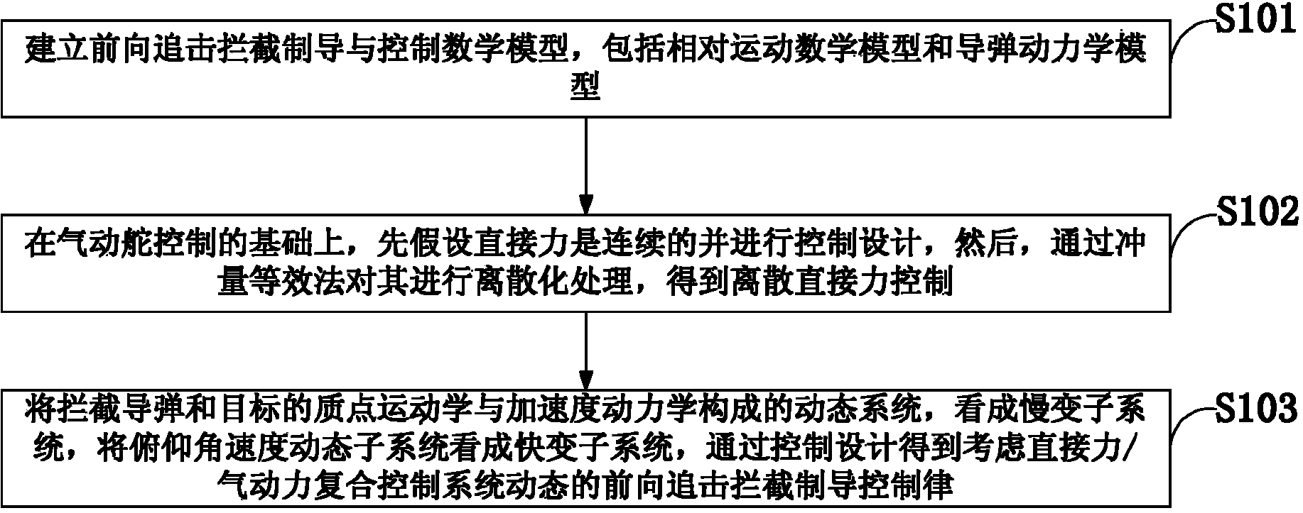
[0168] like figure 1 As shown, the direct force aerodynamic compound control method and the forward interception guidance method in the embodiment of the present invention include the following steps:

[0169] S101: Establish forward pursuit and interception guidance and control mathematical models, including relative motion mathematical models and missile dynamics models;

[0170] S102: On the basis of aerodynamic rudder control, first assume that the direct ...


PUM


Abstract

The invention discloses a direct force and aerodynamic force composite control method and a forward-direction interception guidance method, and provides a direct force design method which carrying out discretization through an impulse equivalence method on the basis of considering characteristics of continuous aerodynamic force and characteristics of discrete direct force, so that a complex control distribution problem is solved. According to a two-dimensional forward-direction interception guidance motion model and an interceptor missile kinetic model and by means of time scale separation, a dynamical system formed by a particle kinematics and accelerated speed slow subsystem of an interceptor missile and a target is regarded as a slow subsystem, a pitch angle speed dynamic subsystem is regarded as a fast subsystem, and a forward-direction interception guidance rule with dynamic conditions of a direct force / aerodynamic force composite control system taken into account is obtained through tracking control design of a pitch angle speed instruction. According to the direct force and aerodynamic force composite control method and the forward-direction interception guidance method, the complex control distribution problem is solved, the dynamic conditions and characteristics of composite control are conveniently taken into account through the design of the forward-direction interception guidance rule, interpolation calculation can be carried out through nominal values of aerodynamic coefficients conveniently, and practical application is convenient.

Description

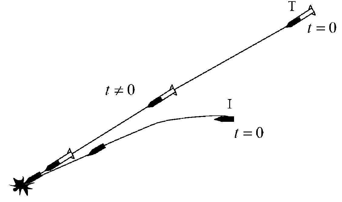
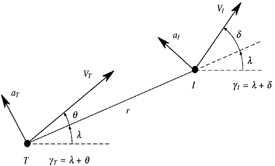
technical field [0001] The invention belongs to the technical field of a direct force control method and an interception guidance law, and in particular relates to a direct force aerodynamic compound control method and a forward interception guidance method. Background technique [0002] For the interception of high-altitude, high-speed and large-moving targets, the typical head-on interception method will make the relative movement speed between the projectile and the target very large, and it is difficult for the seeker to detect the target; hard to accomplish. Therefore, Oded M.Golan et al. proposed a new forward pursuit and interception (Head-Pursuit) guidance method (Oded M.Golan, Tal Shima. Head pursuit guidance for hypervelocity interception[C].Navigation and Control Conference, CP- 4885, AIAA, Washington, DC, 2004:1-12.), divided the interception process into two plane interception problems with mutually perpendicular channels, and established a two-dimensional forw...

Claims


Application Information

Patent Timeline
IPC IPC(8): F41H11/02F42B15/01
Inventor 张友安吴华丽胡云安赵国荣粱勇
Owner NAVAL AERONAUTICAL & ASTRONAUTICAL UNIV PLA
Learn More