Backlight source detection device

A detection equipment and backlight technology, which is applied in the direction of optical instrument testing, optical testing defect/defect, optics, etc., can solve the problems of repeated inspection and missed inspection in the area, so as to improve inspection efficiency, reduce personnel loss, and improve defect detection rate effect

Active Publication Date: 2014-09-03
BOE OPTICAL SCI & TECH +1
View PDF6 Cites 10 Cited by
  • Summary
  • Abstract
  • Description
  • Claims
  • Application Information

AI Technical Summary

Problems solved by technology

[0004] This method is used for backlight lighting inspection. During the inspection process, the hands of the inspector are always in a suspended state, and the work intensity is high. It is impossible to avoid abnormal phenomena caused by fingers touching the surface of the backlight; and there is no relevant standard line reference during the suspension movement, and the distance between back and forth Only through the subjective judgment of the inspectors, repeated inspections or missed inspections often occur in areas

Method used


Image

  • Backlight source detection device
  • Backlight source detection device
  • Backlight source detection device

Examples


Embodiment Construction

[0043] The structure and principle of the present invention will be described in detail below in conjunction with the accompanying drawings, and the examples given are only used to explain the present invention, not to limit the protection scope of the present invention.

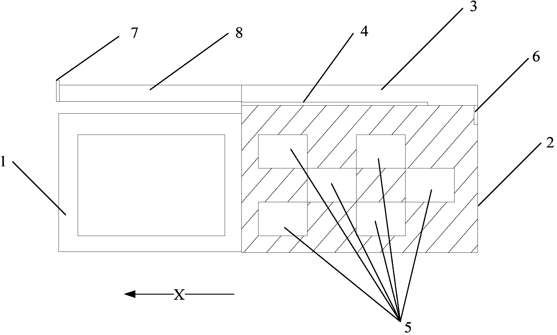
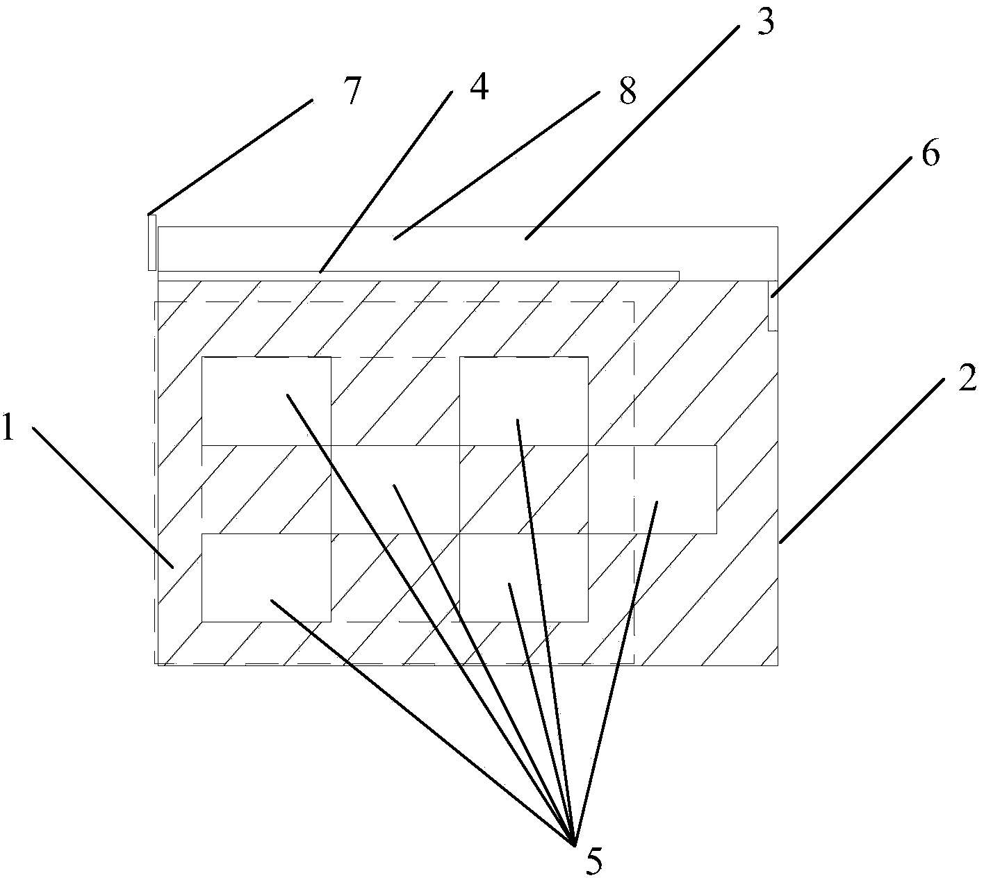
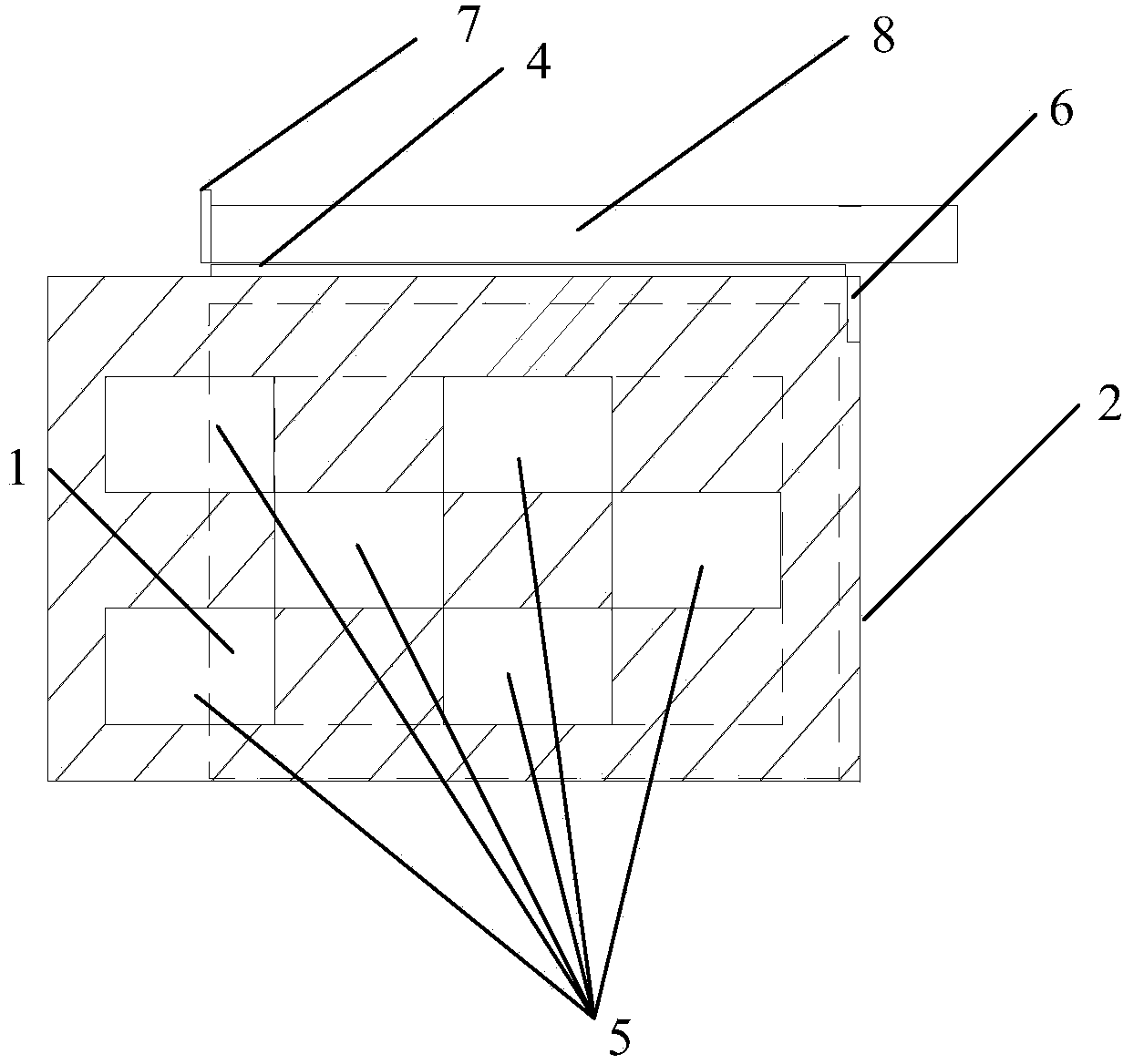
[0044] Such as Figure 1 to Figure 7 As shown, this embodiment provides a backlight detection device, which is characterized in that it includes:

[0045] The carrying platform 1 is used to place the backlight source to be detected; and

[0046] The inspection board 2 is arranged in a movable manner relative to the carrying platform 1, and can move from a first position to a second position;

[0047] When the inspection board 2 is in the first position, it exposes the first light-emitting area of ​​the backlight to be tested, and blocks the second light-emitting area outside the first light-emitting area; when the inspection board 2 is in the second position, A third light-emitting area different from the ...


PUM


Abstract

The invention relates to a backlight source detection device. The backlight source detection device comprises a bearing platform for disposing a backlight source to be detected thereon, and an inspection panel which is arranged in a movable mode relative to the bearing platform and can move to a second position from a first position, wherein when the inspection panel is disposed at the first position, a first luminescence area of the backlight source to be detected is exposed, and a second luminescence area apart from the first luminescence area is shielded; and when the inspection panel is disposed at the second position, a third luminescence area, which is different from the first luminescence area, of the backlight source to be detected is exposed, and a fourth luminescence area apart from the third luminescence area is shielded. The advantages are as follows: the examination difficulty and intensity are reduced, the examination efficiency is improved, through practice examination, the defect detection rate of a large-dimension backlight source is effectively improved, and personnel missed detection is reduced.

Description

technical field [0001] The invention relates to an auxiliary fixture for lighting inspection of a large-size backlight source, in particular to a backlight source detection device. Background technique [0002] In the TFT-LCD industry chain, BLU (backlight source) is an important part of this field, and lighting inspection is required after the BLU assembly is completed. For example, the patent application number: 201010160663 records a backlight lighting test fixture and its use method, wherein one backlight lighting fixture is more suitable for small-sized lighting inspection. [0003] Existing medium and large size backlight inspection mainly relies on manual inspection. The inspection method is that the thumb and forefinger form a "bow" shape, and start to float from the upper left corner of the backlight to form a "Z" movement on the backlight, and the eyes follow the inspector. The movement of the fingers performs a "bow" type test. [0004] This method is used for b...

Claims


Application Information

Patent Timeline
Patent Type & Authority Applications(China)
IPC IPC(8): G01M11/00G02F1/13
CPCG01N21/95G01N21/8806G01N2021/9513G01N2201/02G01N2201/068
Inventor 严志伟曹春雷
Owner BOE OPTICAL SCI & TECH
Why Eureka
Try Eureka