Motor rotor end ring-guide bar medium-frequency induction brazing verifying tooling and method

An induction brazing and motor rotor technology, which is applied in the manufacture of stator/rotor body, etc., can solve problems such as unfavorable timely tracking and verification of rotor brazing quality, affecting mechanical performance test results, and cracking of end ring-bar brazing seams. , to achieve the effect of improving labor productivity and efficiency, saving verification costs, and shortening verification cycles

Active Publication Date: 2014-09-03
CRRC YONGJI ELECTRIC CO LTD
View PDF5 Cites 5 Cited by
  • Summary
  • Abstract
  • Description
  • Claims
  • Application Information

AI Technical Summary

Problems solved by technology

After the brazing of the rotor is completed, use a lathe to cut off the iron core punch and guide bar radially at the center of the total length of the rotor, use a sawing machine to divide the end rings on both sides of the rotor into six parts, and then use a punch and a hand hammer to separate the end ring-guide bar It is time-consuming and labor-intensive to take out the components, and it is easy to crack the end ring-guide bar brazing seam, which will affect the correct judgment of the subsequent mechanical performance test results
The entire rotor needs to be invested in each verification, including core punches, pressure plates, end plates, shafts, end rings, guide bars, solder and flux, etc. The manufacturing cycle is long and the waste is large, which is not conducive to timely tracking and verification of the brazing quality of the rotor

Method used


Image

  • Motor rotor end ring-guide bar medium-frequency induction brazing verifying tooling and method
  • Motor rotor end ring-guide bar medium-frequency induction brazing verifying tooling and method

Examples


Embodiment Construction

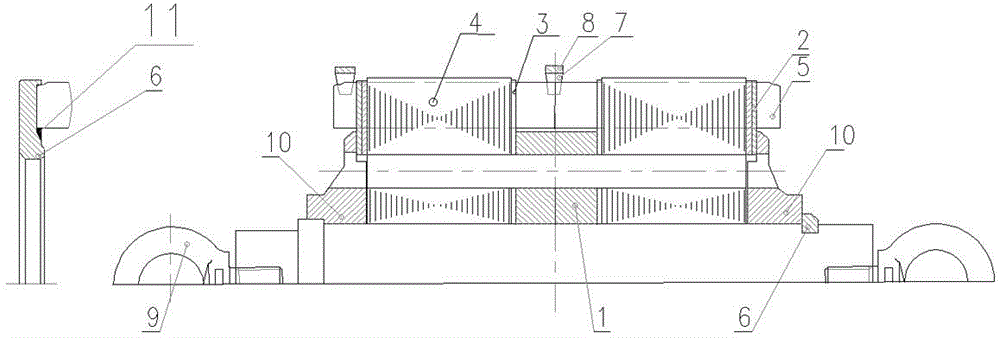
[0029] An intermediate frequency induction brazing verification tool for motor rotor end ring guide bar according to the present invention, such as figure 1 , figure 2 As shown, it includes rotor separator 1, rotor end plate I2 and rotor end plate II3. The rotor separator 1 is arranged in the middle of the rotor core punch 4, which separates the rotor core punch 4 and the guide bar 5 into two parts, realizing the split structure of the verification tooling. After adding the rotor separator, the local core punches are reduced, and the increase After brazing, the ring-guide bar joint assembly opens up the operating space to reduce the contact area between the guide bar and the iron core punch. The outer circumference of the guide bar 5 at the position of the rotor separator 1 is wrapped with asbestos cloth to realize the simulation brazing of the rotor verification tooling and the actual whole process. Consistency of heat loss and quality during brazing of Taiwan rotor product...


PUM


Abstract

The invention relates to a motor rotor end ring-guide bar medium-frequency induction brazing verifying tooling, comprising a rotor separator, rotor end plates I and rotor end plates II, wherein the rotor separator is arranged in the middle of a rotor core punching plate, and divides the rotor core punching plate and a guide bar into two parts; the outer diameter of the rotor separator is smaller than the inner diameter of a circle on which the guide bar is located; the rotor end plates I with pre-pressing curved radians are respectively arranged at the sides of the end rings at two sides; the rotor end plates II are respectively arranged at two sides of the rotor separator. The end ring-guide bar component after being brazed is smoothly taken out by adopting a split structure by combining with the structure characteristics of a traditional motor rotor, the manufacturing period is short, time and labor are saved, just the end rings, the guide bar, a silver solder and a welding agent need to be fed, the motor rotor end ring-guide bar medium-frequency induction brazing verifying tooling can be repeatedly utilized, and is large in operation space, and convenient to maintain, and verification of the performance of the actual motor rotor end ring-guide bar medium-frequency induction brazing product is met.

Description

technical field [0001] The invention relates to the verification of a motor, in particular to a verification tool and a verification method for an intermediate frequency induction brazing of a motor rotor end ring guide bar. Background technique [0002] Most of the CRH2 / 3 / 5 motor car motors, HXD2 / 3 and HXN3 squirrel cage rotor end rings and guide bars of locomotive motors adopt overall intermediate frequency induction brazing. Practical and efficient rotor end ring-guide bar overall intermediate frequency induction brazing technology is the key to meet the technology introduction of motor manufacturing, regular or irregular verification of its brazing quality becomes an important guarantee for effective monitoring of rotor brazing quality. The pros and cons of verifying rotor brazing technology directly affect the quality, labor productivity and benefits of this type of motor rotor. [0003] In the same industry of motors at home and abroad, the quality verification of...

Claims


Application Information

Patent Timeline
Patent Type & Authority Applications(China)
IPC IPC(8): H02K15/02
Inventor 谢贵生时兴华赵东超吴学鹏
Owner CRRC YONGJI ELECTRIC CO LTD
Why Eureka
Try Eureka