AC permanent magnet synergistic reluctance motor

A reluctance motor, permanent magnet technology, applied to synchronous motors with static armatures and rotating magnets, magnetic circuit rotating parts, synchronous machines, etc., can solve the problem of insufficient permanent magnet energy.

Active Publication Date: 2014-02-05
戴珊珊
View PDF6 Cites 38 Cited by
  • Summary
  • Abstract
  • Description
  • Claims
  • Application Information

AI Technical Summary

Problems solved by technology

Although the emergence of rare earth permanent magnet materials and the rapid development of permanent magnet motors in various fields, many potentials of permanent magnet energy have not been fully exploited.

Method used


Image

  • AC permanent magnet synergistic reluctance motor
  • AC permanent magnet synergistic reluctance motor
  • AC permanent magnet synergistic reluctance motor

Examples


Embodiment 1

[0074] Embodiment 1: This embodiment provides a unipolar permanent magnet synergistic reluctance motor whose rotor adopts a single-sided cantilever bracket and whose stator adopts compound excitation salient pole pairs. Its structure and shape are shown in the attached Figure 6-8 shown.

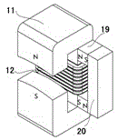
[0075] The stator of this embodiment is composed of a stator base 17 and four "composite excitation salient pole pairs", which are respectively arranged up, down, left, and right, with a gap of 90 degrees between them. "Composite excitation salient pole pair" consists of a "C-shaped" laminated iron core 11, an excitation coil 12 and a permanent magnet assembly 19, 20, as attached figure 2 As shown, the two port faces of the "C-shaped laminated iron core" face up and down, and the two port faces are arc-shaped. When the input excitation current of the excitation coil is zero, there is no magnetic polarity at the upper and lower port faces of the "C-shaped" laminated iron core, and the two m...

Embodiment 2

[0079] Embodiment 2: This embodiment provides a permanent magnet synergistic reluctance motor in which the rotor is a double-sided cantilever bracket and the stator compound excitation salient pole pair is unipolar. Its shape and structure are as follows: Figure 12-14 shown.

[0080] This embodiment is a special case of the first embodiment, that is, the combined structure of the motor shafts given in the two first embodiment.

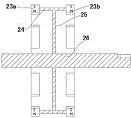
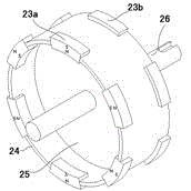
[0081] This embodiment adopts double-sided cantilever rotor support, and its structure is as attached Figure 9-11 As shown, the magnetic polarities of adjacent permanent magnets located on the same side of the support and on the same rotating surface are different, while the magnetic polarities of the two permanent magnets located on both sides of the support and at the same central angle are the same.

[0082] The eight compound excitation salient pole pairs of the motor stator in this embodiment are divided into two groups, with the disk in the ro...

Embodiment 3

[0085] Embodiment 3: This embodiment provides another permanent magnet synergistic reluctance motor in which the rotor is a double-sided cantilever support and the stator composite excitation salient pole pair is unipolar. The structure and setting of the composite excitation salient pole pair on the stator The position is the same as that of embodiment two (see attached Figure 13-14 shown).

[0086] The difference between the present embodiment and the second embodiment is that the setting rules of the permanent magnets on the double-sided cantilever brackets are different, as shown in the attached Figure 15 And attached Figure 16 As shown, there is still a difference of 60 degrees between the radial centerlines of the six permanent magnets on one side of the cantilever bracket, and the magnetic polarity of two adjacent permanent magnets is different, but the six permanent magnets on one end of the cantilever bracket The permanent magnets and the six permanent magnets at...


PUM


Abstract

The invention relates to an AC permanent magnet synergistic reluctance motor. The motor is characterized in that permanent magnets or permanent magnet components are combined with laminated cores in stator excitation salient pole pairs; when excitation coils do not have excitation current, the permanent magnets or the permanent magnet components and the laminated cores in the excitation salient pole pairs form locally closed magnetic circuits; when the excitation coils have the excitation current, the original closed permanent magnet magnetic circuits are opened and converged on the excitation magnetic circuits of the excitation salient pole pairs, and then compound excitation magnetic potential is produced on the two port surfaces of each salient pole of each excitation salient pole pair; when the magnetic port surfaces of the permanent magnets fixed to a rotor support are just opposite or coincide with the port surfaces of the stator excitation salient pole pairs, the shortest closed magnetic circuit with air gaps is formed. According to the AC permanent magnet synergistic reluctance motor, the magnetic induction intensity in the air gaps of the motor is greatly increased, the torque at the time of low rotation speed is increased, common magnetic circuit interference and flux leakage are reduced, electric energy is saved, and the power density of the motor and the use rate of equipment are further enhanced.

Description

technical field [0001] The invention relates to a reluctance motor, in particular to an AC permanent magnet synergistic reluctance motor capable of combining permanent magnet flux and excitation flux. Background technique [0002] The electric motor is a product with a large quantity and a wide range. Its coverage covers all fields of the national economy such as industry and agriculture, transportation, aerospace, military industry and national defense, commercial households, etc. It has become an important part of most mechanical transmission methods and industrial modernization. Base. The performance of the motor will be directly related to the national economic benefits, energy consumption and the protection of the ecological environment. Therefore, the pursuit of a high-efficiency, low-consumption, stable and reliable, easy-to-control, and low-cost excellent motor has become the goal pursued by motor research institutions, experts, and engineering technicians all over ...

Claims


Application Information

Patent Timeline
Patent Type & Authority Applications(China)
IPC IPC(8): H02K21/00H02K21/16H02K1/17H02K1/27
Inventor 戴珊珊朱石柱
Owner 戴珊珊
Why Eureka
Try Eureka