Arm joint structure of small underwater hydraulic manipulator

A technology of joint structure and robotic arm, applied in the direction of manipulators, manufacturing tools, joints, etc., which can solve the problems of fewer operating manipulators, the structure of the manipulator arm is only applicable, and cannot meet the requirements of underwater operations, etc., to achieve strong driving ability and large rotation The effect of small angle, volume and weight

Inactive Publication Date: 2014-09-10
HARBIN ENG UNIV
View PDF8 Cites 10 Cited by
  • Summary
  • Abstract
  • Description
  • Claims
  • Application Information

AI Technical Summary

Problems solved by technology

At present, the autonomous underwater vehicle (AUV) has become a research hotspot due to its advantages such as a wide range of environments. However, due to limitations in size, weight and energy, there are very few operating manipulators suitable for AUVs; Strong miniaturized hydraulic manipulators are especially rare
[0003] At present, most domestic manipulator arm structures adopt "U-shaped plate frame" and "cylindrical" structures, and most of the manipulator drive methods use motor drive and hydraulic drive; Driven by a motor, the structure is relatively simple and the flexibility is good, but the structure of the manipulator arm is only suitable for land manipulators, which cannot meet the requirements of underwater operations, and cannot meet the requirements of miniaturization of manipulators; for example, the Chinese patent application number is 200620086859.X The name is the manipulator arm, the manipulator adopts several sets of parallel four-bar linkage structure, and the hydraulic cylinder drives the manipulator to realize the movement of the manipulator's approximate vertical lifting and approximate horizontal telescopic movement; but it cannot realize the joint rotation of the manipulator by 180°, and the manipulator structure cannot be miniaturized

Method used


Image

  • Arm joint structure of small underwater hydraulic manipulator
  • Arm joint structure of small underwater hydraulic manipulator
  • Arm joint structure of small underwater hydraulic manipulator

Examples


Embodiment Construction

[0025] The present invention will be described in further detail below in conjunction with the accompanying drawings.

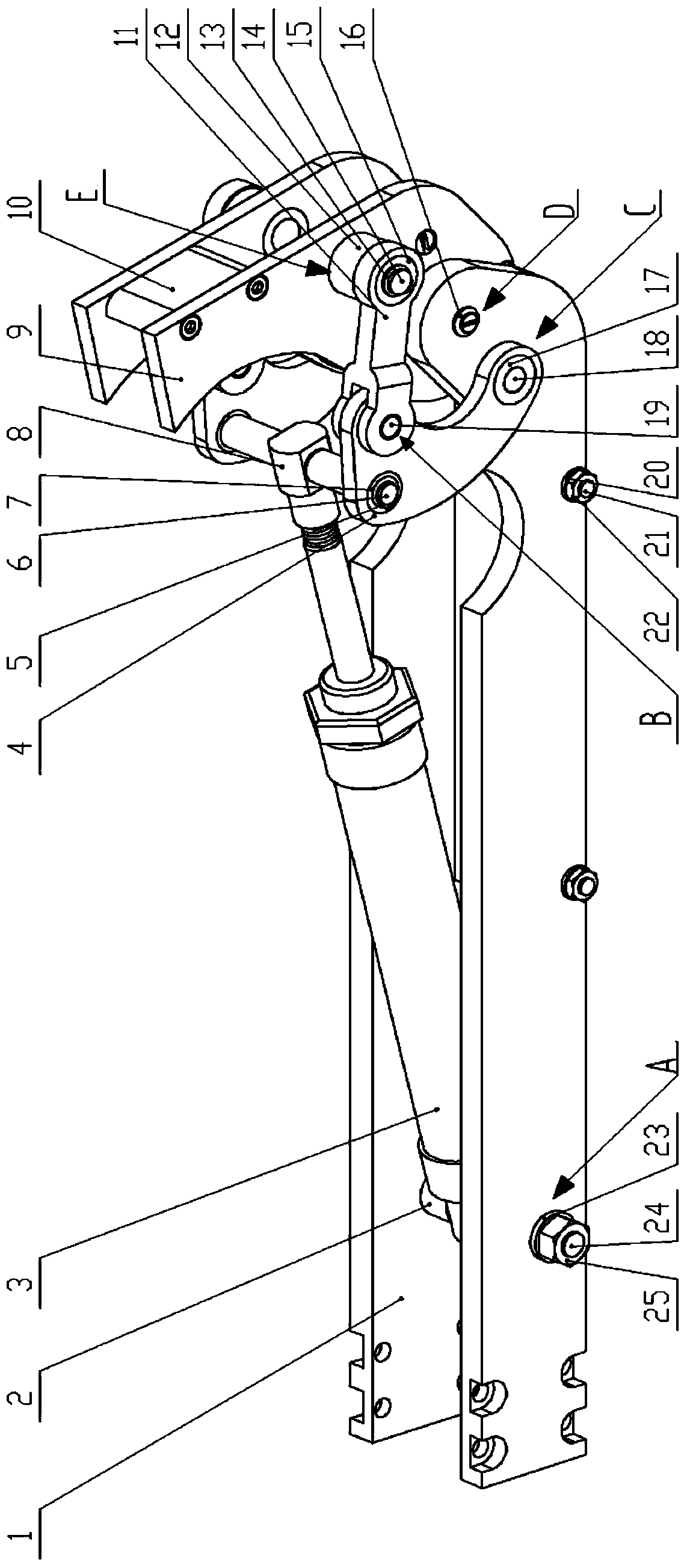
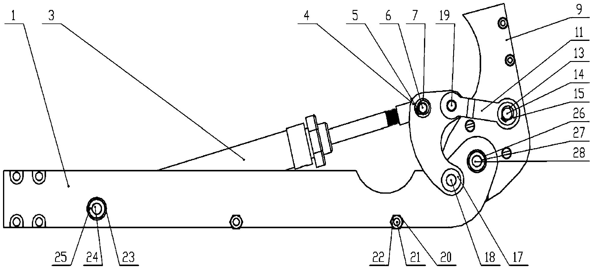
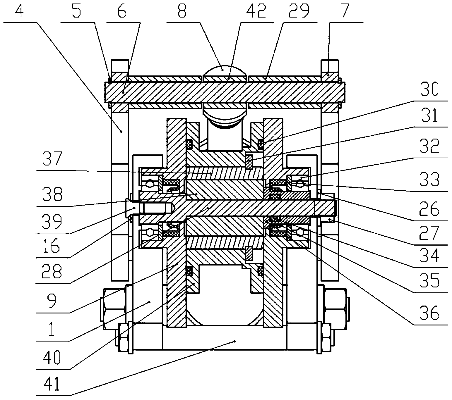
[0026] An important part of the underwater hydraulic manipulator of the present invention provides the manipulator with the driving force for underwater operations, and feeds back operating parameters such as the angle and angular acceleration of the manipulator's joints through its own position detection device to facilitate the control of the manipulator joints by the host computer; The patent of the invention adopts oil-hydraulic drive six-point mechanism, so that the joint can rotate up to 180°, which can provide a relatively large and stable driving torque for the manipulator, and has a compact structure, small volume and weight, and meets the design requirements for the miniaturization of the manipulator. .

[0027] The present invention adopts the oil-hydraulic drive mode, and the manipulator joint is mainly composed of four parts: the manipulator arm,...


PUM


Abstract

The invention relates to an arm joint structure of a small underwater hydraulic manipulator, which comprises a first mechanical arm, a second mechanical arm and a drive mechanism, wherein the front end of the first mechanical arm is connected with the rear end of the second mechanical arm via a rotation shaft; the drive mechanism is arranged between the first mechanical arm and the second mechanical arm and comprises a hydraulic cylinder, a C-shaped plate and a straight plate; a cylinder body of the hydraulic cylinder is articulated with the first mechanical arm; a cylinder rod is articulated with the middle of the C-shaped plate; one end of the C-shaped plate is articulated with the first mechanical arm; the other end of the C-shaped plate is articulated with one end of the straight plate; and the other end of the straight plate is articulated with the second mechanical arm. The arm joint structure has the advantages of compact structure, small size, convenience in mounting, flexible joint driving and strong driving power, can achieve 180-degree rotation of a manipulator joint, and is applicable to driving the small underwater hydraulic manipulator joint.

Description

technical field [0001] The invention relates to a manipulator arm joint structure, in particular to a miniaturized underwater hydraulic manipulator arm joint structure mounted on an underwater robot. Background technique [0002] Underwater robot is an important tool for modern marine environment monitoring and resource development; with the continuous improvement of its working scope and operating requirements, higher requirements are also put forward for its operating tools. At present, the autonomous underwater vehicle (AUV) has become a research hotspot due to its advantages such as a wide range of environments. However, due to limitations in size, weight, and energy, there are few operating manipulators suitable for AUVs; Strong miniaturized hydraulic manipulators are especially rare. [0003] At present, most domestic manipulator arm structures adopt "U-shaped plate frame" and "cylindrical" structures, and most of the manipulator drive methods use motor drive and hydr...

Claims


Application Information

Patent Timeline
Patent Type & Authority Applications(China)
IPC IPC(8): B25J17/02B25J13/08
Inventor 张铭钧杨超马小委赵克楠刘兵
Owner HARBIN ENG UNIV
Why Eureka
Try Eureka