Insert positioning structure in die

A technology of insert positioning and mold, which is applied in the direction of coating, etc., can solve problems such as easy scratches and material leakage, affect product quality and performance, and product scrapping, so as to prevent material leakage, improve quality and pass rate, prevent strong sticky effect

Active Publication Date: 2014-09-10
SHANGHAI ROX ELECTRIC
View PDF5 Cites 2 Cited by
  • Summary
  • Abstract
  • Description
  • Claims
  • Application Information

AI Technical Summary

Problems solved by technology

The positioning structure of the insert in the mold is crucial, which not only affects the feasibility and convenience of the mold operation, but also affects the quality and performance of the product, and can even directly lead to the scrapping of the product
Larger tubular inserts are characterized by large volume and heavy weight. It is very difficult to position on the mold, and it is easy to scratch and leak materials, which makes it difficult to guarantee product quality.

Method used


Image

  • Insert positioning structure in die
  • Insert positioning structure in die

Examples


Embodiment Construction

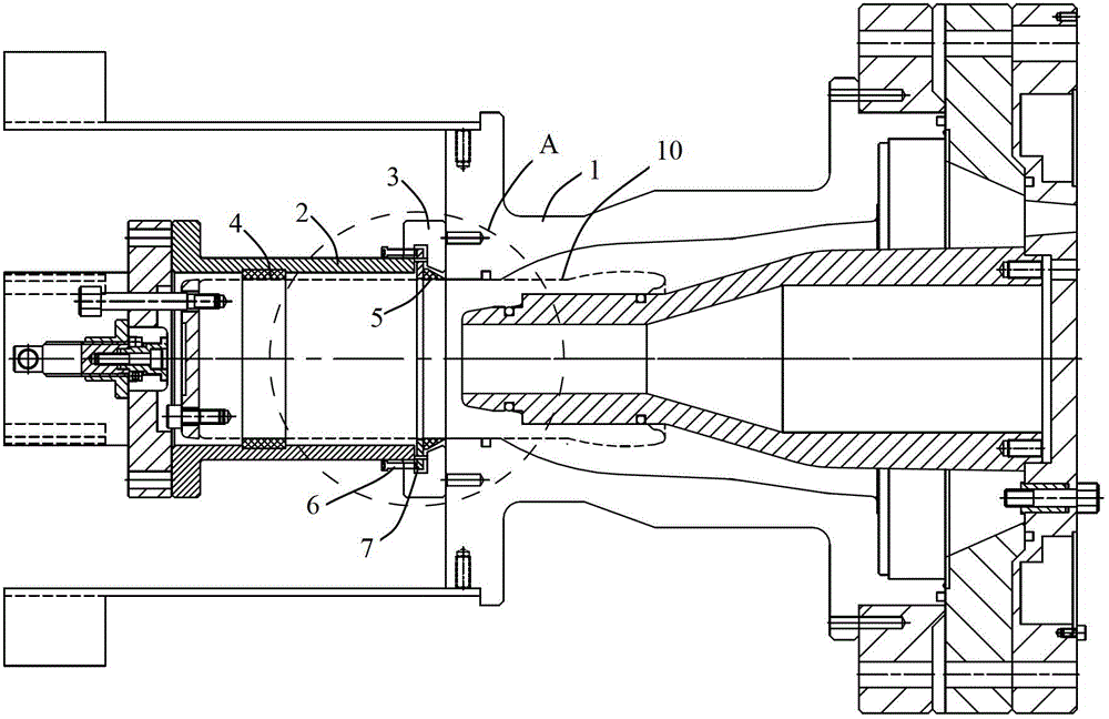
[0012] Such as figure 1 As shown, the insert positioning structure in the mold of the present invention includes a sleeve 2 and a block 3, the block 3 is annular, the sleeve 2 is fixedly connected to the block 3, and the block 3 is connected to the mold The body 1 is fixedly connected. The sleeve 2 is provided with at least one positioning groove (not shown in the figure) along the circumferential direction of the sleeve, and the first polytetrafluoroethylene protective sleeve 4 is installed in the positioning groove, as shown in the figure, the A positioning groove is arranged inside the casing 2, and a first polytetrafluoroethylene protective sleeve 4 is correspondingly arranged in the positioning groove. A second polytetrafluoroethylene protective sheath 5 is arranged inside the block 3 .

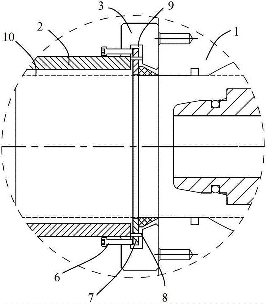
[0013] As a preferred solution, in the present invention, the inner surface of the block 3 is provided with a groove 9 along the circumferential direction of the block, and the groove ...


PUM


Abstract

The invention discloses an insert positioning structure in a die. The insert positioning structure comprises a bushing and a seal block, the bushing is fixedly connected with the seal block, and the seal block is fixedly connected with the body of the die; at least one positioning slot along the circumference direction of the bushing is arranged in the bushing, and a first polytetrafluoroethylene protection sleeve is arranged in the positioning slot; and a second polytetrafluoroethylene protection sleeve is arranged in the seal block. The insert positioning structure in the die realizes the convenience of the installation and positioning of the insert, and can prevent material leakage.

Description

technical field [0001] The invention relates to the positioning of mold inserts in the APG process, in particular to an insert positioning structure in a mold. Background technique [0002] The APG process refers to the epoxy resin automatic pressure gel process, that is, the process of heating the epoxy resin to make it thermoset. [0003] At present, the insulation parts of medium and high voltage electrical equipment are generally processed by APG process. In order to increase the product strength, metal parts are usually embedded in the injection molding process. The positioning structure of the insert in the mold is crucial, which not only affects the feasibility and convenience of mold operation, but also affects the quality and performance of the product, and can even directly lead to the scrapping of the product. Larger tubular inserts are characterized by large volume and heavy weight. It is very difficult to position on the mold, and it is easy to scratch and leak...

Claims


Application Information

Patent Timeline
IPC IPC(8): B29C45/26B29C45/14B29K63/00
CPCB29C45/14065
Inventor 徐元贵马强费龙菲刘昌军
Owner SHANGHAI ROX ELECTRIC
Why Eureka
Try Eureka