Forming equipment of plastic material filled with polyurethane foam in core layer

A technology of plastic profiles and molding equipment, which is applied in the field of plastic profile molding equipment, can solve problems such as reduced heat insulation, and achieve the effects of improving heat insulation, reducing costs, and simplifying assembly processes

Active Publication Date: 2014-09-10
DALIAN HUAGONG INNOVATION TECH
View PDF8 Cites 12 Cited by
  • Summary
  • Abstract
  • Description
  • Claims
  • Application Information

AI Technical Summary

Problems solved by technology

[0003] In order to overcome the deficiencies of the prior art, the present invention provides a plastic profile molding equipment with core layer filled with polyurethane foam. The plastic profile manufactured by the equipment of the present invention solves the problem of heat insulation reduction caused by air convection, and improves the Thermal insulation, sound insulation effect and structural strength of plastic doors and windows

Method used


Image

  • Forming equipment of plastic material filled with polyurethane foam in core layer
  • Forming equipment of plastic material filled with polyurethane foam in core layer
  • Forming equipment of plastic material filled with polyurethane foam in core layer

Examples


specific Embodiment approach 1

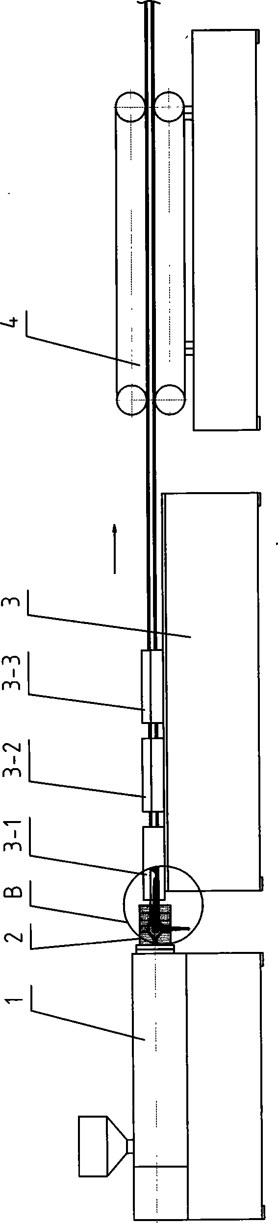
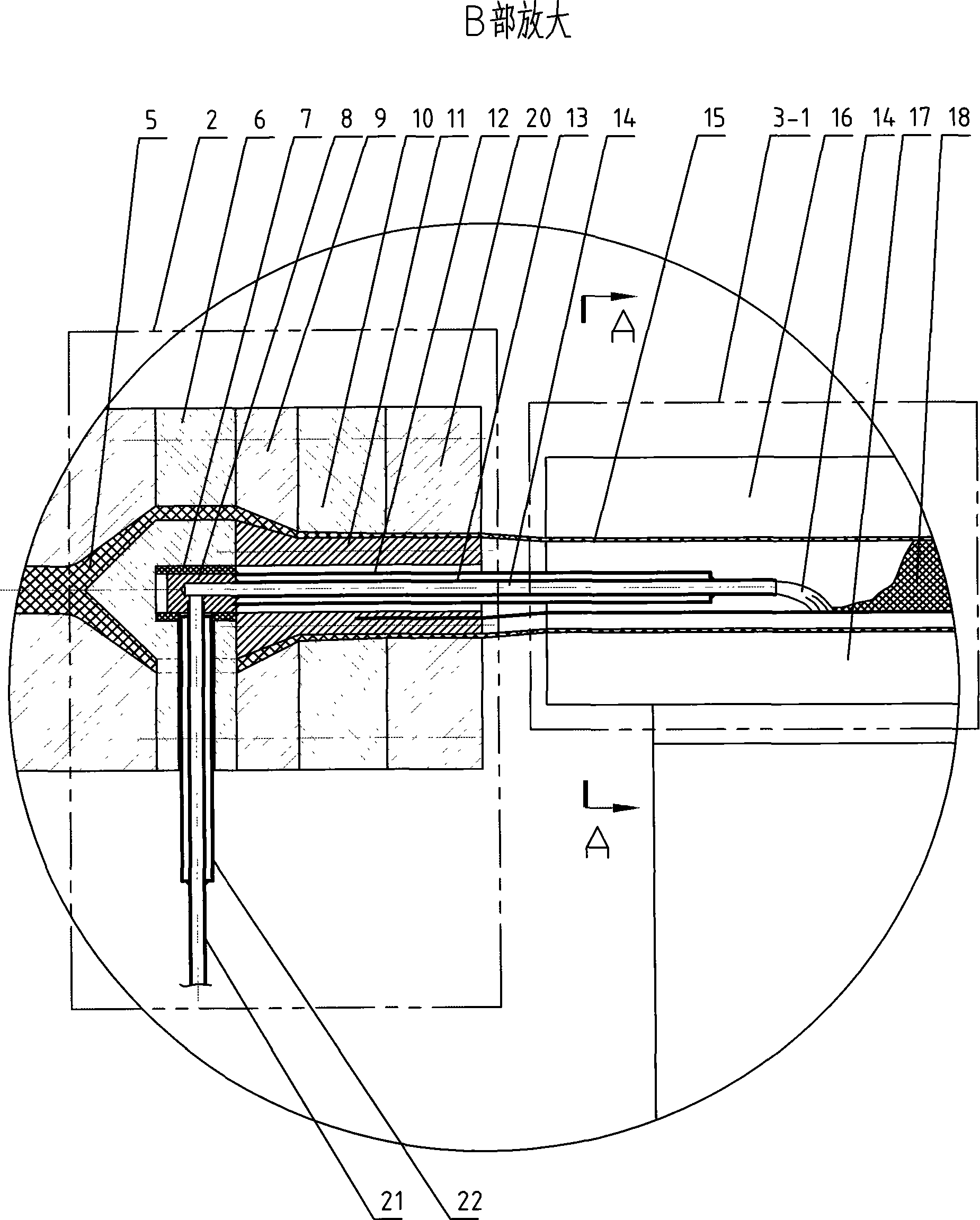
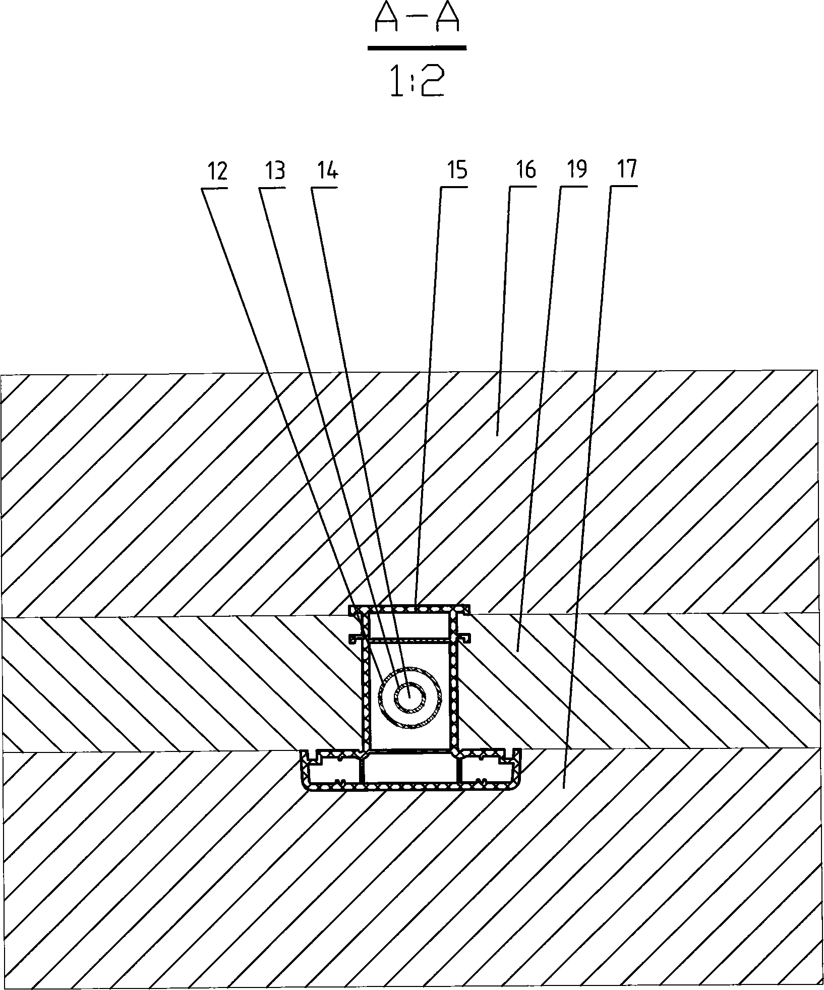
[0010] Specific implementation mode one: as Figure 1 to Figure 5 As shown, the core layer filled polyurethane foam plastic profile molding equipment described in this embodiment includes an extruder 1, a head 2, a cooling and setting device 3, a tractor 4, etc., and the head 2 includes a sub-fluid 6 and a template A9 , template B10, template C20, mandrel 11 and polyurethane feed channel, cooling and setting device 3 comprises cooling mold A3-1, cooling mold B3-2 and cooling mold C3-3, and machine head 2 is fixed on the machine of extruder 1 At the end of the cylinder, there is a polyurethane feeding channel inside the machine head 2, and the polyurethane feeding channel includes a heat insulating ring 7, a connecting piece 8, a polyurethane feeding pipe A13, a heat insulating pipe A12, a polyurethane feeding pipe B21, and a heat insulating pipe B22 , the connecting piece 8 is concentrically connected with the polyurethane feed pipe A13 and the heat insulating pipe A12, the he...

specific Embodiment approach 2

[0011] Specific implementation mode two: as Figure 4 , Figure 5 As shown, the section of the plastic profile 24 in this embodiment has a closed cavity 23, the cavity 23 of the plastic profile 24 is surrounded by a plurality of surfaces, and the closed cavity 23 is filled with polyurethane foam. The foam body 18 and the polyurethane foam body 18 are injected into the larger cavity 23 of the space. Other components and connections are the same as those in the first embodiment.

specific Embodiment approach 3

[0012] Specific implementation mode three: as Figure 4 , Figure 5 As shown, the cross-sectional shape represented by the plastic profile 24 in this embodiment is only one kind, and it can be a commercially available plastic profile with other cross-sectional shapes. The layer is filled with a polyurethane foamed plastic profile 24 . Other components and connections are the same as those in the first embodiment.


PUM


Abstract

The invention provides forming equipment of a plastic material filled with polyurethane foam in a core layer, and relates to forming equipment of plastic door and window materials. The forming equipment comprises an extruder, a machine head, a cooling shaping device, tractor and the like, wherein the machine head comprises a shunt body, a template A, a template B, a template C, a core mold and a polyurethane feeding channel; the polyurethane feeding channel is formed in the machine head, and comprises a heat insulating ring, a connecting piece, a polyurethane feeding pipe A, a heat insulating pipe A, a polyurethane feeding pipe B and a heat insulating pipe B; the connecting piece is concentrically and fixedly connected with the polyurethane feeding pipe A and the heat insulating pipe A; the heat insulating pipe A is concentrically and fixedly connected outside the polyurethane feeding pipe A; and a space between the heat insulating pipe A and the polyurethane feeding pipe A is closed or vacuumized. The plastic material produced by the equipment solves the problem of low heat insulation property caused by the cross-ventilation, and improves the heat insulation property, sound insulation effect and structural strength of plastic doors and windows.

Description

technical field [0001] The invention relates to a plastic profile forming equipment with a core layer filled with polyurethane foam, which is mainly used for manufacturing plastic door and window profiles. Background technique [0002] At present, there are many types of plastic door and window profile molding equipment at home and abroad, mainly extruding PVC profiles. When extruding profiles, single extrusion is the main one, and there are also two or three co-extrusion profiles. In the manufacture of plastic doors and windows, in order to increase the strength, the method of placing steel lining in the inner cavity of the plastic profile is adopted. The plastic profile and the steel lining are connected by screws, the strength increase is not high, and the on-site construction is troublesome. In addition, the inner cavity of the plastic profile is due to Air convection reduces the thermal insulation performance and also affects the thermal insulation effect of doors and w...

Claims


Application Information

Patent Timeline
Patent Type & Authority Applications(China)
IPC IPC(8): B29C47/56B29C44/18B29C47/12B29C48/30
CPCB29C48/0012B29C48/30B29C48/87
Inventor 韩毅军时丕林刘桂红
Owner DALIAN HUAGONG INNOVATION TECH
Why Eureka
Try Eureka