Photoresist plastic bottle caps and plastic bottles

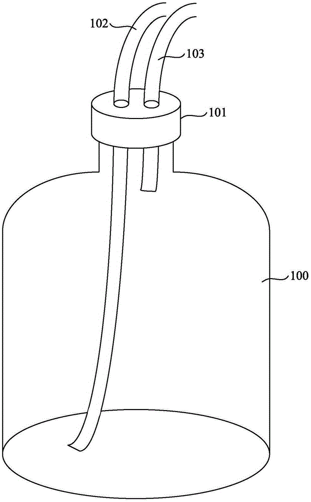
A technology for photoresist and plastic bottles, applied in the field of photoresist plastic bottle caps and plastic bottles, can solve the problems of wafer shortage, limitation, glue supply pipeline 102 and return pipeline 103 cannot be fixed, etc. Achieve the effects of improving production pass rate, avoiding wafer shortage, and simple equipment improvement

Active Publication Date: 2016-05-25
ADVANCED SEMICON MFG CO LTD
View PDF5 Cites 0 Cited by
  • Summary
  • Abstract
  • Description
  • Claims
  • Application Information

AI Technical Summary

Problems solved by technology

[0003] However, the existing glue supply method is limited by the structure of the glue bottle cover 101, so that the glue supply pipeline 102 and the return pipeline 103 cannot be fixed, and the glue supply pipeline 102 is often not inserted into the bottom of the glue bottle 100 (i.e. The glue pipeline 102 is often suspended), resulting in evacuation when supplying glue to the glue coating equipment, and the wafer (wafer) on the machine is short of glue

Method used


Image

  • Photoresist plastic bottle caps and plastic bottles
  • Photoresist plastic bottle caps and plastic bottles
  • Photoresist plastic bottle caps and plastic bottles

Examples


Embodiment Construction

[0019] The present invention will be further described below in conjunction with specific embodiment and accompanying drawing, set forth more details in the following description so as to fully understand the present invention, but the present invention can obviously be implemented in many other ways different from this description, Those skilled in the art can make similar promotions and deductions based on actual application situations without violating the connotation of the present invention, so the content of this specific embodiment should not limit the protection scope of the present invention.

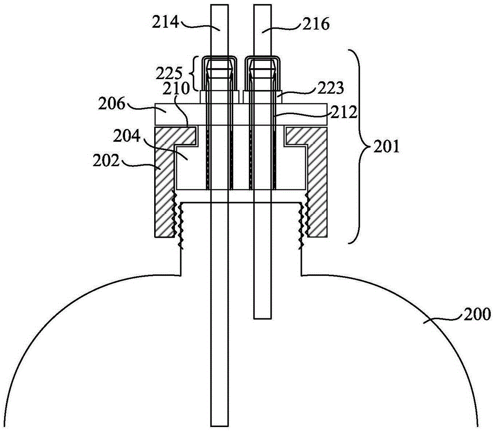
[0020] figure 2 It is a schematic cross-sectional structure diagram of a cap of a photoresist glue bottle used for supplying glue to glue application equipment according to an embodiment of the present invention. It should be noted that this and other subsequent drawings are only examples, which are not drawn according to the same scale, and should not be taken as limitations ...


PUM


Abstract

The invention provides a cap of a photoresist bottle and the photoresist bottle. The cap of the photoresist bottle comprises a bottle cap body, a cap core, a cover plate and a photoresist tube guide locking piece. The bottle cap body is connected with the opening of the photoresist bottle in a threaded mode through threads on the inner side of the lower portion of the bottle cap body. The cap core is located above the opening and on the inner side of the upper portion of the bottle cap body. The cover plate is located above the bottle cap body and the cap core and fixed to the cap core. An annular groove is formed between the cover plate and the cap core, the front end of the upper portion of the bottle cap body is embedded into the annular groove, and therefore the bottle cap body and the cover plate can neither be separated nor rotate independently, and the bottle cap body and the cap core can neither be separated nor rotate independently. Vertically-through holes are formed in the cap core and the cover plate, the photoresist tube guide locking piece penetrates through the holes and is fixed to the cap core and / or the cover plate in a threaded mode. The photoresist tube guide locking piece is hollow, and a photoresist tube guiding photoresist penetrates through the photoresist tube guide locking piece to be inserted into the photoresist bottle by a proper depth and is fixed to bottle cap body in a locking mode. According to the cap of the photoresist bottle and the photoresist bottle, the photoresist tube can be fixed to the cap of the photoresist bottle, evacuation caused when the photoresist tube can not be inserted to the bottom of the photoresist bottle is prevented, and therefore photoresist shortage of wafers is avoided.

Description

technical field [0001] The invention relates to the technical field of semiconductor manufacturing equipment, in particular, the invention relates to a photoresist plastic bottle cover and a plastic bottle. Background technique [0002] figure 1 It is a three-dimensional structure schematic diagram of a photoresist glue bottle cover used for supplying glue to glue application equipment in the prior art. Such as figure 1 As shown, the glue supply mode of the existing glue coating equipment (not shown) is to drill two holes on the glue bottle cover 101 of the photoresist glue bottle 100, so that the glue supply pipeline (outlet) 102 and the return pipeline ( Vent) 103 extend into the glue bottle 100 through the glue bottle cover 101 of the hole respectively, to realize the functions of glue supply and return flow. [0003] However, the existing glue supply method is limited by the structure of the glue bottle cover 101, so that the glue supply pipeline 102 and the return pi...

Claims


Application Information

Patent Timeline
Patent Type & Authority Patents(China)
IPC IPC(8): B65D47/06
Inventor 邹剑平
Owner ADVANCED SEMICON MFG CO LTD
Why Eureka
Try Eureka