Drawing vacuum melting furnace capable of continuous molding and discharging

A vacuum melting furnace, drawing technology, applied in the field of drawing vacuum melting furnace, can solve secondary molding and other problems

Active Publication Date: 2019-10-25
石棉达升再生资源有限公司
View PDF5 Cites 0 Cited by
  • Summary
  • Abstract
  • Description
  • Claims
  • Application Information

AI Technical Summary

Problems solved by technology

[0003] The purpose of the present invention is to provide a drawing-type vacuum smelting furnace capable of continuous molding and discharging, so as to solve the problem that secondary molding is often required when industrial silicon is used in the prior art, and realize one-time molding in the vacuum smelting process without secondary molding , the purpose of cost reduction

Method used


Image

  • Drawing vacuum melting furnace capable of continuous molding and discharging
  • Drawing vacuum melting furnace capable of continuous molding and discharging
  • Drawing vacuum melting furnace capable of continuous molding and discharging

Examples


Embodiment 1

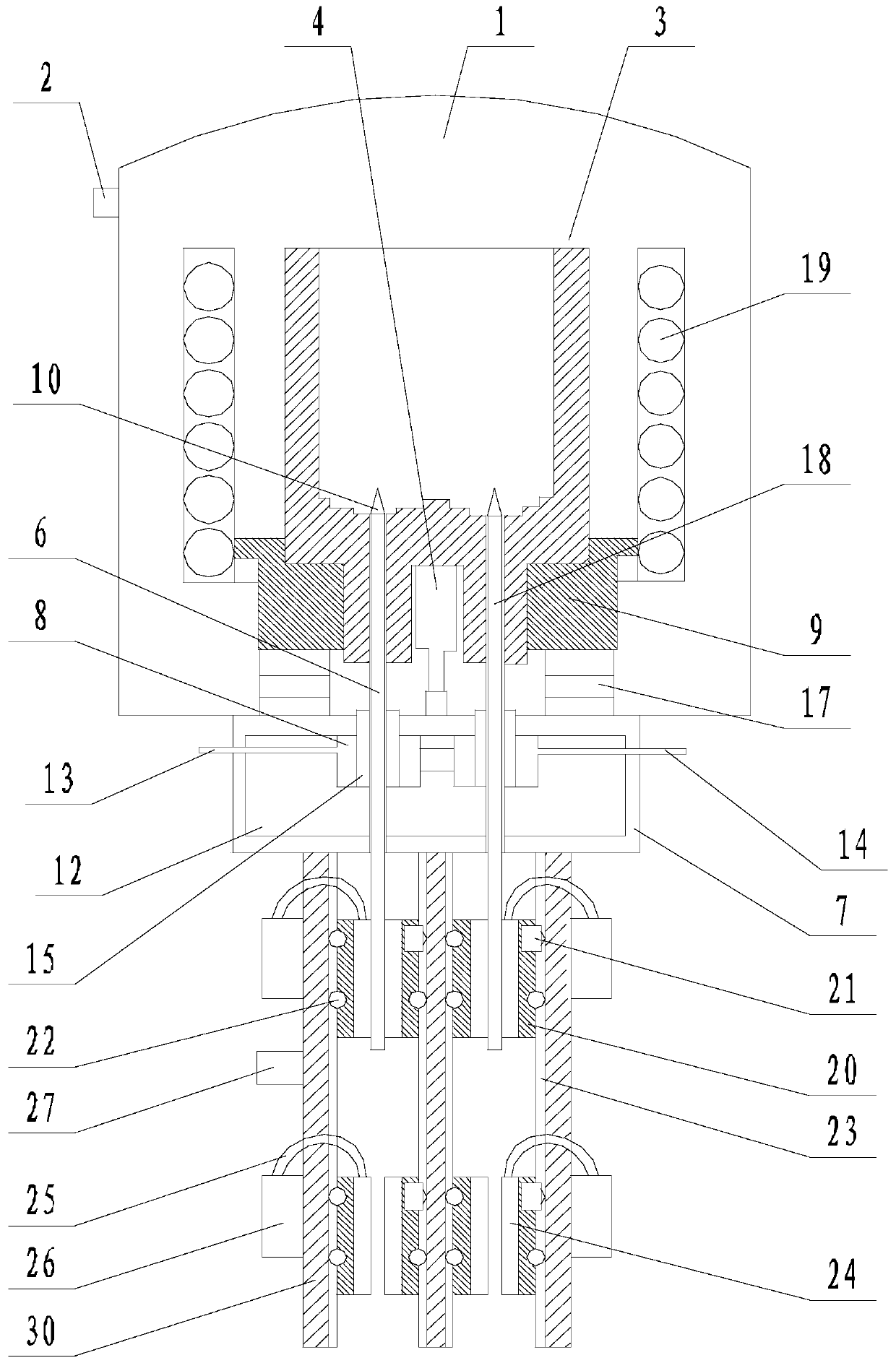
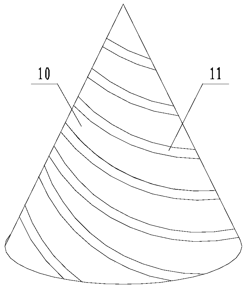
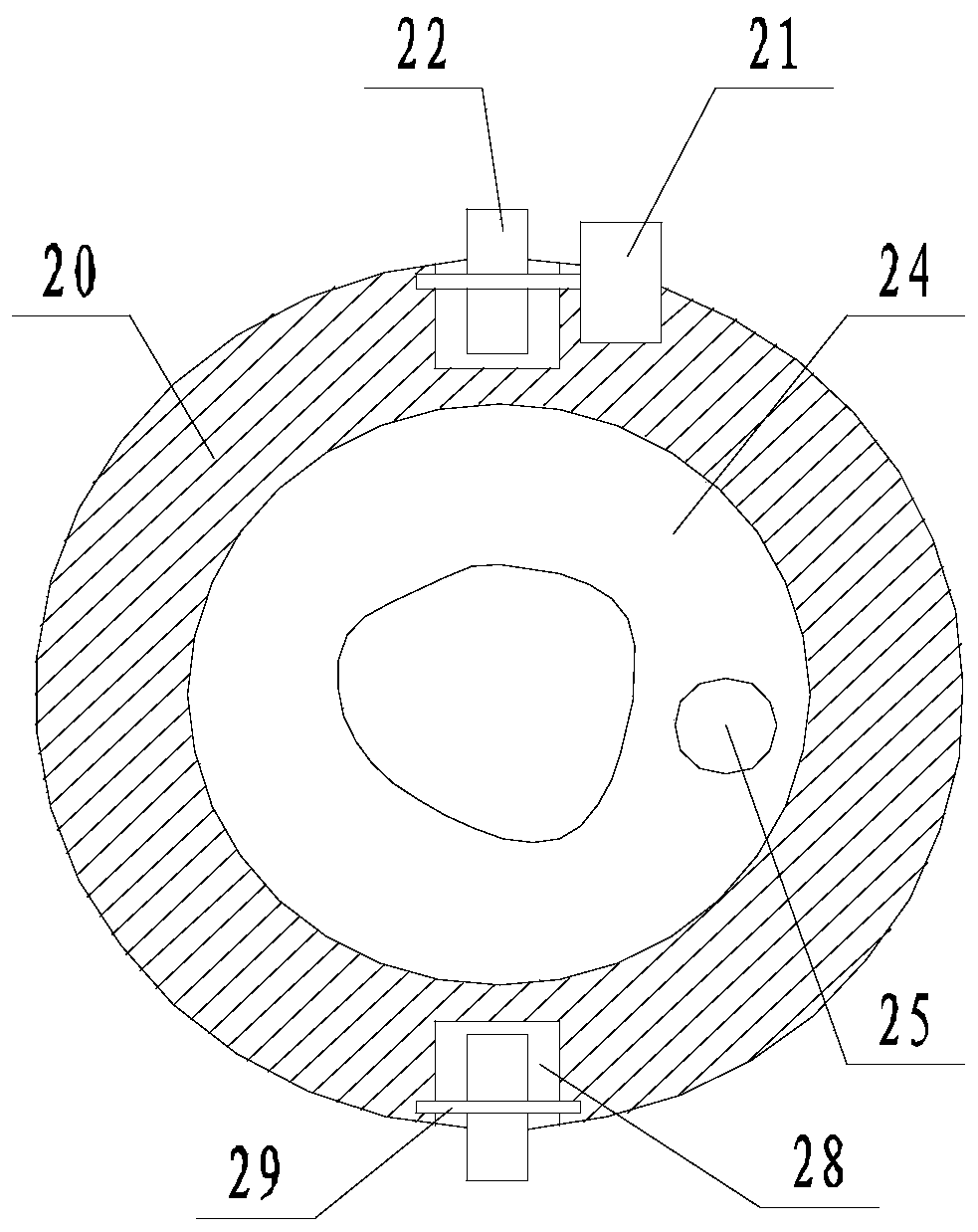
[0030] Such as Figure 1 to Figure 3 The shown drawing-type vacuum melting furnace capable of continuous molding and discharging includes a furnace body 1 with a vacuum suction port 2, a crucible 3 is arranged in the furnace body 1, and an induction heating coil 19 is located outside the crucible 3. The inner bottom surface of the furnace body 1 is provided with a pushing device 4 with the output end facing upwards. The output end of the pushing device 4 is in contact with the bottom of the crucible 3, and the bottom of the crucible 3 is provided with a discharge pipe that runs through the bottom surface of the crucible 3. A drawing rod 6 is arranged in the tube, the cross section of the drawing rod 6 matches the cross section of the discharge pipe, a crystallization chamber 7 is arranged under the furnace body 1, and a water cooling box is arranged on the top surface of the crystallization chamber 7 8. The discharge pipe passes through the water-cooled box 8, and the bottom e...

Embodiment 2

[0032] Such as Figure 1 to Figure 4 In the drawing-type vacuum melting furnace capable of continuous molding and discharging, on the basis of Example 1, a groove is provided on the bottom surface of the crucible 3, and the output end of the pushing device 4 is located in the groove. The crystallization chamber 7 is surrounded by metal plates, and the crystallization chamber 7 is filled with thermal conductive silicone grease 12 . The water cooling box 8 is connected with a water inlet pipe 13 and an outlet pipe 14 , and both the water inlet pipe 13 and the water outlet pipe 14 extend to the outside of the crystallization chamber 7 . The outlet pipe 5 is covered with a silicone sleeve 15 , and the silicone sleeve 15 is fixed on the bottom of the furnace body 1 . The bottom surface of the discharge pipe 5 is flush with the bottom surface of the crystallization chamber 7 , and the discharge pipe 5 is covered with a sealing ring 16 , and the sealing ring 16 is fixedly connected ...


PUM


Abstract

The invention discloses a drawing type vacuum smelting furnace with continuous forming and discharging functions. The drawing type vacuum smelting furnace is characterized in that the shapes of the cross sections of discharging pipes are set according to the shape of a silicon sectional material needing to be obtained, drawing rods move downwards along the discharging pipes so as to suck a moltenliquid in a crucible, the liquid is driven to gradually fill the discharging pipes and flow downwards, when the liquid flows to the position where a water cooling box is located, the liquid is forcedto be cooled by the water cooling box, the liquid is solidified in a short time when the liquid passes through a crystallization chamber, and finally, the solidified liquid is guided out from the bottom ends of the discharging pipes along with the drawing rods so as to obtain the industrial silicon material with the specified cross section shape. According to the drawing type vacuum smelting furnace, two sleeves which are distributed up and down are arranged below each discharging pipe, the two sleeves are controlled to alternately move up and down in the respective forming range, then uninterrupted continuous drawing of the silicon material can be realized, the silicon material smelted in the crucible is made into a complete and continuous integral structure once, and the automation degree and the finished product integrity are greatly improved.

Description

technical field [0001] The invention relates to the field of vacuum smelting furnaces, in particular to a drawing-type vacuum smelting furnace capable of continuous molding and discharging. Background technique [0002] Vacuum smelting refers to a special smelting technology that smelts under vacuum conditions. It mainly includes vacuum induction melting, vacuum arc remelting and electron beam melting. With the rapid development of modern science and technology, especially with the rapid progress of aerospace, ocean development, energy development and electronic industry, there are higher and higher requirements for the variety, output and especially quality of metal materials or non-metal materials . Vacuum smelting needs to be carried out in a vacuum smelting furnace. For the smelting of industrial silicon, castings are obtained by casting in molds after smelting. However, this method cannot directly obtain profiles and can only meet the needs of existing silicon bricks....

Claims


Application Information

Patent Timeline
Patent Type & Authority Patents(China)
IPC IPC(8): F27B14/04F27B14/06F27B14/18F27D3/14C01B33/02
CPCC01B33/02F27B14/04F27B14/061F27B14/0806F27B2014/045F27B2014/0818F27D3/145
Inventor 羊实庹开正
Owner 石棉达升再生资源有限公司
Why Eureka
Try Eureka