Wire cutter chain transmission tensioning assistance device

A technology of chain drive and auxiliary device, applied in the direction of conveyor, transportation and packaging, can solve the problems of shutdown, difficult to adjust the locking of the support plate 13, and the tensioning device can not be effectively tensioned, so as to achieve easy installation, Simple structure, no maintenance required

Active Publication Date: 2014-09-10
CHINA TOBACCO ANHUI IND CO LTD
View PDF6 Cites 3 Cited by
  • Summary
  • Abstract
  • Description
  • Claims
  • Application Information

AI Technical Summary

Problems solved by technology

The adjustment mechanism of the first pressure chain wheel 6 is as image 3 As shown, the wheel shaft of the first pressure chain wheel 6 is fixed on the support 10, and the support is fixedly connected with the adjustment support plate 11. The adjustment support plate can be slid on the machine base 12 and locked with bolts, but in practical applications, the bolts It is difficult to lock the adjusting support plate 11 with the base 12
The adjustment mechanism of the third pressure chain wheel 8 is as Figure 4 As shown, the wheel shaft of the third pressure chain wheel 8 is fixed on the adjustable support plate 13, and the adjustable support plate 13 is provided with a long groove 14 as a slideway, and the support plate 15 is provided with locking bolts, and the adjustable support plate 13 adjusts its position on the support plate 15 through its slideway, and locks it through the locking bolt. In the same way, it is difficult for the locking bolt to lock the adjustable support plate 13
However, in the tensioning device of the chain drive, the design and manufacturing concept of this type of shredder still follow the old-fashioned traditional way, adopting a simple design concept and extensive tensioning method, which makes the shortcomings and defects of the chain drive more exposed. Undoubtedly, in production, this type of shredding machine often occurs and shuts down due to the failure of the main transmission system, and the main reason for this phenomenon is that the tensioning device cannot effectively play a tensioning role.

Method used


Image

  • Wire cutter chain transmission tensioning assistance device
  • Wire cutter chain transmission tensioning assistance device
  • Wire cutter chain transmission tensioning assistance device

Examples


Embodiment

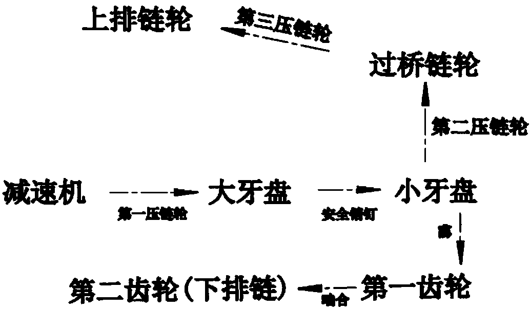
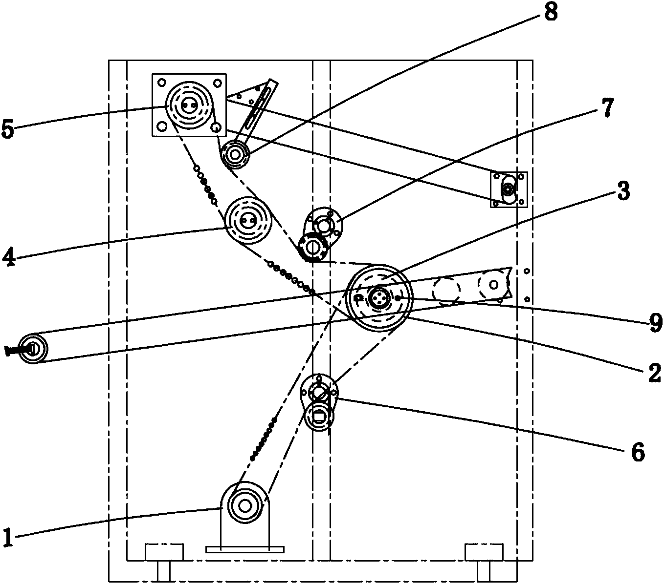
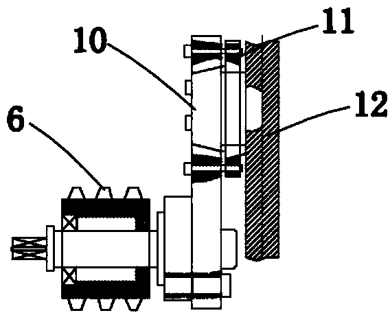
[0019] Embodiment: In conjunction with the accompanying drawings, the chain drive tensioning auxiliary device of the shredding machine of this embodiment, wherein, the chain transmission mechanism of the shredding machine includes: the sprocket on the output shaft of the reducer 1 is connected with the big crankset 2 through a chain, and the big crankset 2. It is coaxially connected with the small tooth plate 3 through the safety pin 9. The first gear is installed on the small tooth plate 3 through a key. The first gear meshes with the second gear to transmit the power to the lower chain; It is connected with the bridge crankset 4, and the bridge crankset 4 is connected with the upper sprocket 5 through the chain, and the power is transmitted to the upper chain, and the first pressure sprocket 6 is arranged on the chain between the reducer and the large crankset , the chain between the small chainring 3 and the bridge chainring 4 is provided with a second pressure sprocket 7, a...


PUM


Abstract

The invention discloses a wire cutter chain transmission tensioning assistance device. A wire cutter chain transmission mechanism is characterized in that a chain wheel on a speed reducer output shaft is connected with a big crankset through a chain, the big crankset is coaxially connected with a small crankset through a safety pin, a first gear is mounted on the small crankset through a key and meshed with a second gear to transmit power to a lower row chain wheel, a first chain pressing wheel is arranged on the chain between a speed reducer and the big crankset, a second chain pressing wheel is arranged on a chain between the small crankset and a bridging crankset, and a third chain pressing wheel is arranged on a chain between the bridging crankset and an upper row chain wheel. A lifting and lowering adjustment mechanism provided with the first chain pressing wheel and a tensioning mechanism provided with the third chain pressing wheel can freely adjust a tensioning device without stopping running or producing to guarantee stable working and normal running of a transmission system.

Description

Technical field: [0001] The invention relates to a chain drive tensioning auxiliary device of a shredding machine. Background technique: [0002] The tensioning device of the transmission chain of the shredding machine takes into account the principles of energy saving, environmental protection, and consumer health protection, fully embodying the performance of environmental protection and safety and sanitation. Due to the different control methods, there are obvious differences in their applicability on the machine. figure 1 , 2 As shown, the driving of the upper and lower copper bar chains in the material conveying system of this model is the reducer 1 with a servo motor as the power source, and the sprocket on the output shaft of the reducer 1 is connected to the large crankset 2 through a chain. The large crankset 2 and the small crankset 3 are coaxially connected through the safety pin 9, and the first gear is installed on the small crankset 3 through a key, and the f...

Claims


Application Information

Patent Timeline
Patent Type & Authority Applications(China)
IPC IPC(8): B65G23/44
Inventor 王建新陈万里邵伟尹杰力徐黎明陈文明陈继富汪涛
Owner CHINA TOBACCO ANHUI IND CO LTD
Why Eureka
Try Eureka