Rotating region detection device, system and detection method

A technology of area detection and slip ring, which is applied in the direction of transportation and packaging, load hanging components, etc., to achieve the effect of low cost, simple and easy transformation, and wide application range

Inactive Publication Date: 2014-09-10
XCMG XUZHOU TRUCK MOUNTED CRANE
View PDF10 Cites 1 Cited by
  • Summary
  • Abstract
  • Description
  • Claims
  • Application Information

AI Technical Summary

Problems solved by technology

[0003] In order to solve the technical problems existing in the prior art, the object of the present invention is to provide a new detection device, method and system for the slewing area, so as to solve the problem that the user can detect without installing additional sensors such as proximity switches or encoders. Technical Problems in Realizing the Detection of Rotary Area

Method used


Image

  • Rotating region detection device, system and detection method
  • Rotating region detection device, system and detection method
  • Rotating region detection device, system and detection method

Examples


Embodiment 1

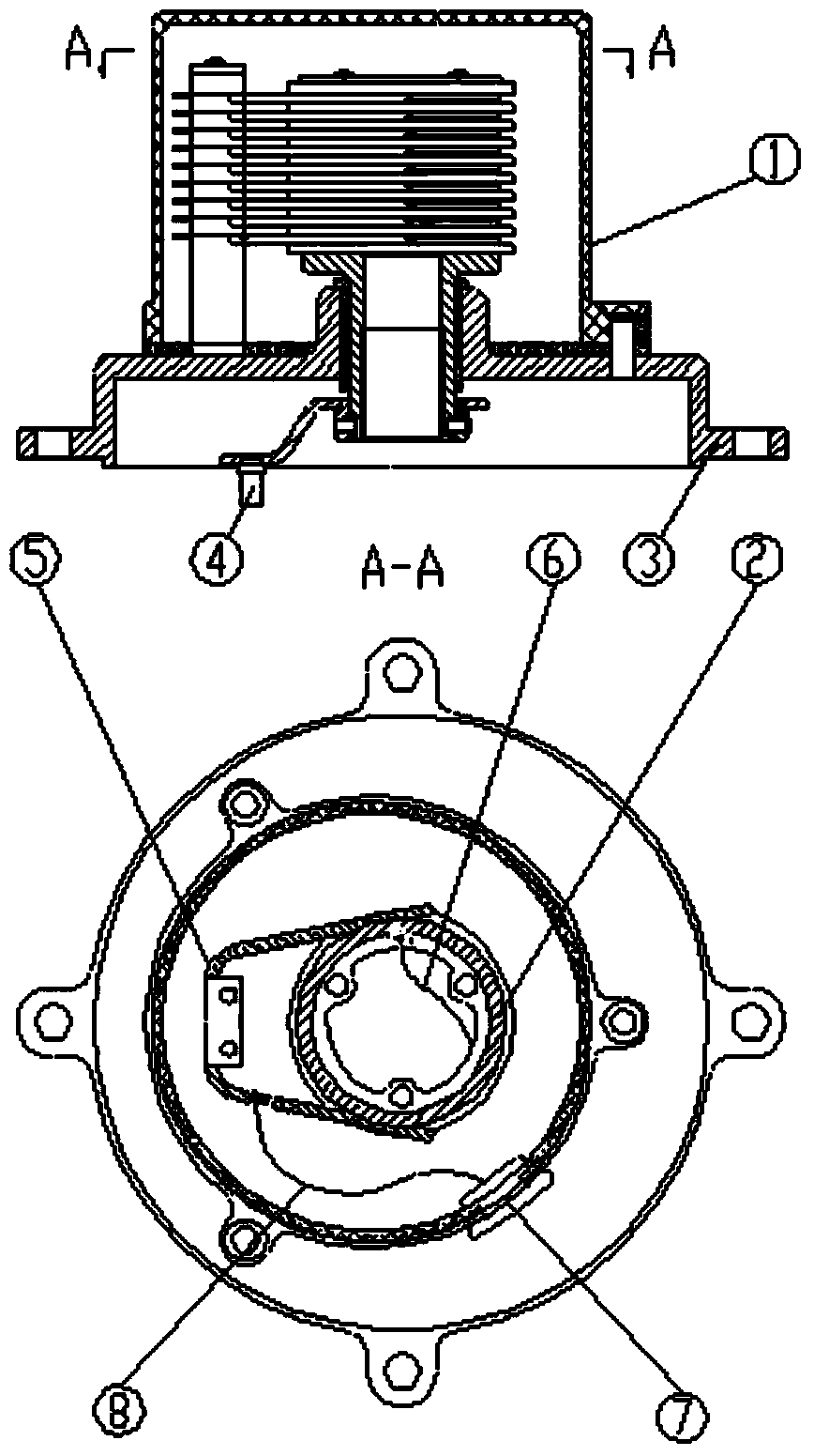
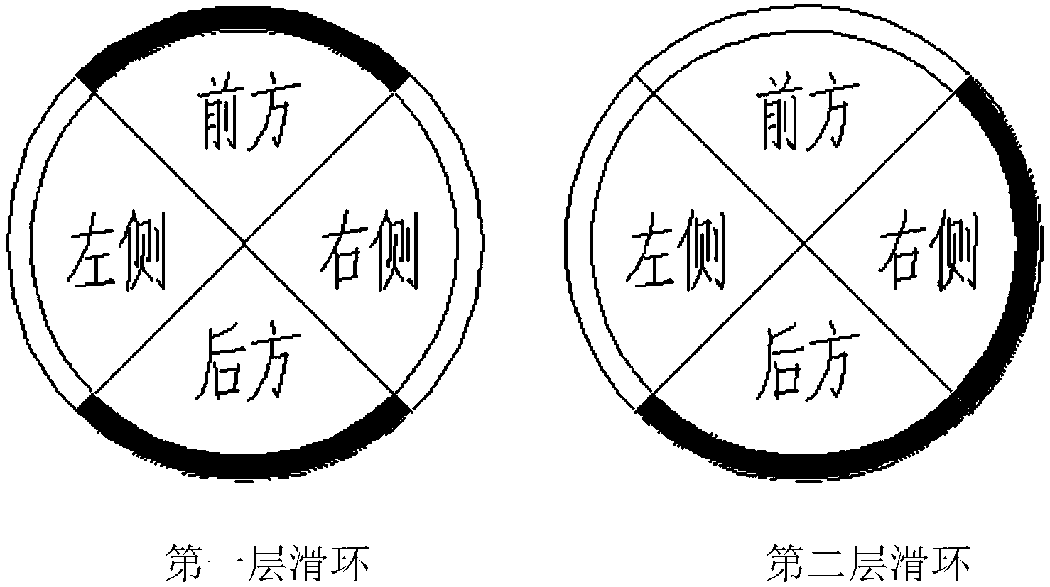
[0031] Such as image 3 As shown, the black slip ring area filled with conductive material is called the conductive part, while the slip ring area not filled with conductive material is called the insulating part. During the relative sliding process of the brush body 5 and the slip ring 2, the brush body 5 passes through the conductive part of the black slip ring and conducts the circuit, and transmits a high-level signal to the controller, which is recorded as 1, and the brush body 5 passes through the insulating part of the non-filled slip ring The circuit is not conducting, and a low-level signal is transmitted to the controller, which is recorded as 0. image 3 The first slip ring and the second slip ring in the front, rear, left and right sides are divided into equal parts, the first slip ring is set as a conductive part at the front and rear, and is set as an insulating part at the left and right . The second slip ring is provided as a conductive part on the right and ...

Embodiment 2

[0034] The following takes the anti-overturn control of the truck-mounted crane as an example for a brief description. In this example, the installation position of the truck-mounted crane is close to the rear side of the cab of the car. For details, see Figure 4 . In order to realize the overturn protection of the truck-mounted crane, the control equipment needs to collect external sensor information, and apply different control functions f in the 90° area of ​​the front, 60° area of ​​the rear, 105° area on the left side, and 105° area on the right side 1 (x,m), f 2 (x,m), f 3 (x,m) and f 4 (x,m) to calculate and limit the moment, if using such as Figure 5 As shown in the structure of the first layer slip ring and the second layer slip ring, the controller collects the first and second slip ring signals to form different level signal combinations. According to the combined information of these level signals, the area where the slewing device is located can be judged, ...


PUM


Abstract

The invention belongs to the technical field of the mechanical detection, and particularly relates to rotating region detection device, system and detection method. The rotating region detection device comprises a first brush body, a second brush body, a first layer of slide ring and a second layer of slide ring; the two layers of slide rings and the two layers of brush bodies simultaneously slide relatively; the first layer of slide ring is in single-point contact with the first brush body, the second layer of slide ring is in single-point contact with the second brush body, the first layer of slide ring and the second layer of slide ring are respectively of a structure consisting of conductor parts and insulator parts, which are alternately arranged, and the structure of the first layer of slide ring is different from that of the second layer of slide ring. By adopting the device, the technical problem for detecting the rotating region under the situation that no additional sensors such as an approaching switch or an encoder are installed can be solved.

Description

technical field [0001] The invention belongs to the technical field of mechanical detection, and in particular relates to a detection system and a detection method of a rotary area. Background technique [0002] Many work tools have a full-turn mechanism, and different control strategies need to be adopted for the front, rear, left, and right sides in terms of control. At present, the commonly used rotary area detection at home and abroad mainly relies on the installation of proximity switches or encoders at the rotary. In the method of installing a proximity switch at the turning point to detect the turning area, the installation mechanism is relatively complicated and the detection is not reliable enough. Although the installation of the encoder is reliable and easy, the cost is relatively high. Contents of the invention [0003] In order to solve the technical problems existing in the prior art, the object of the present invention is to provide a new detection device,...

Claims


Application Information

Patent Timeline
Patent Type & Authority Applications(China)
IPC IPC(8): B66C13/16
Inventor 程磊孙进陈志伟单龙林园园邹炳福王宝珠
Owner XCMG XUZHOU TRUCK MOUNTED CRANE
Why Eureka
Try Eureka