Medicine bottle cap packing device
A technology for bottle caps and medicine bottles, applied in flange-type bottle caps and other directions, can solve the problems of unfavorable aluminum foil cap clamping efficiency, inconvenient use and maintenance of bottle cap packaging machines, etc. Effective maintenance and tightening efficiency
- Summary
- Abstract
- Description
- Claims
- Application Information
AI Technical Summary
Problems solved by technology
Method used
Image
Examples
Embodiment 1
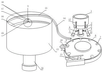
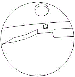
[0028] like Figure 1 to Figure 3 , the medicine bottle cap packaging device provided by the present invention comprises a bottle conveying mechanism, a bottle cap tightening mechanism and a cap conveying mechanism. An ampoule bayonet 7 arranged on the edge of the turntable 9;
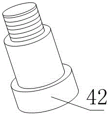
[0029]The bottle cap tightening mechanism includes a rotating shaft 1, a tightening wheel 4, a first rotating shaft 2, an elastic portion 6, a return spring 12 and a pull rod 3, and the tightening wheel 4 includes a tightening wheel seat 41 and a rolling wheel 42, so The rolling wheel 42 is fixed on the tightening wheel seat 41 and can roll around the axis of the tightening wheel seat 41, the rotating shaft 1 is keyed to the first rotating shaft 2, and the first rotating shaft 2 can slide along the axial direction of the rotating shaft 1, The tightening wheel seat 41 is hingedly connected to the first rotating shaft 2, and one end of the elastic part 6 is fixedly connected to the end face of the first...
Embodiment 2
[0033] This embodiment is further limited on the basis of embodiment 1: as Figure 1 to Figure 3 , the pull rod 3 and the tightening wheel 4 are more than one, and the number of the two is equal, and one end of each pull rod 3 is hingedly connected with the elastic part 6, and the other end of each pull rod 3 is respectively connected to a tightening wheel 4 The tightening wheel seat 41 is hingedly connected. The above setting makes it unnecessary for the scroll wheel 42 to form a deformed ring on the aluminum foil cover after turning a full circle, which is beneficial to the working efficiency of the present invention. In order to further optimize the above-mentioned solution for improving working efficiency, the tightening wheels 4 are uniformly distributed in a ring shape, and the center of the ring-shaped uniform distribution is located on the axis of the first rotating shaft 2 . The above settings make it possible to set three tightening wheels 4 in the present invention...
Embodiment 3
[0035] The present embodiment is further limited on the basis of embodiment 1: as Figure 1 to Figure 3 , the tightening wheel seat is a two-section combined structure, one section of the tightening wheel seat is hingedly connected to the first rotating shaft, and the other section is threadedly connected to the one section. The above structure facilitates the replacement of rolling wheels of different sizes according to different aluminum foil covers, which is beneficial to the scope of application of the present invention.
PUM
 Abstract
Description
Claims
Application Information
 - R&D
- Intellectual Property
- Life Sciences
- Materials
- Tech Scout
- Unparalleled Data Quality
- Higher Quality Content
- 60% Fewer Hallucinations
Browse by: Latest US Patents, China's latest patents, Technical Efficacy Thesaurus, Application Domain, Technology Topic, Popular Technical Reports.
© 2025 PatSnap. All rights reserved.Legal|Privacy policy|Modern Slavery Act Transparency Statement|Sitemap|About US| Contact US: help@patsnap.com


