Aluminum foil cap packing mechanism

An aluminum foil cap and packaging technology, which is applied in the direction of flanged bottle caps, etc., can solve the problems of unfavorable clamping efficiency of aluminum foil caps, inconvenient use and maintenance of bottle cap packaging machines, etc., and achieve the benefits of wrapping efficiency, simple operation and maintenance , the effect of simple structure

Active Publication Date: 2014-09-10
CHINA CHENGDU ANIMAL HUSBANDRY IND BIOPHARM
View PDF7 Cites 2 Cited by
  • Summary
  • Abstract
  • Description
  • Claims
  • Application Information

AI Technical Summary

Problems solved by technology

[0004] In order to solve the problem that the bottle cap packaging machine in the prior art is inconvenient to use and maintain, and it

Method used


Image

  • Aluminum foil cap packing mechanism
  • Aluminum foil cap packing mechanism
  • Aluminum foil cap packing mechanism

Examples


Example Embodiment

[0025] Example 1:

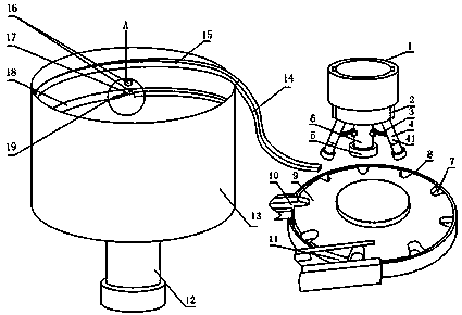
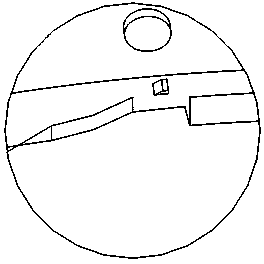
[0026] like Figure 1 to Figure 3 , the aluminum foil cap packaging mechanism provided by the present invention includes a bottle conveying mechanism, a bottle cap tightening mechanism and a cap conveying mechanism, and the bottle conveying mechanism includes a barrel-shaped turntable barrel 8, a turntable 9 arranged in the turntable barrel 8, and a The ampoule bayonet 7 on the edge of the turntable 9;

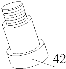
[0027] The bottle cap tightening mechanism includes a rotating shaft 1, a tightening wheel 4, a first rotating shaft 2, an elastic portion 6 and a pull rod 3, and the tightening wheel 4 includes a tightening wheel seat 41 and a rolling wheel 42, and the rolling wheel 42 It is fixed on the tightening wheel seat 41 and can roll around the axis of the tightening wheel seat 41. The rotating shaft 1 is keyed to the first rotating shaft 2, and the first rotating shaft 2 can slide along the axial direction of the rotating shaft 1 to tighten the wheel seat. 41 is...

Example Embodiment

[0030] Example 2:

[0031] This embodiment is further limited on the basis of embodiment 1: as Figure 1 to Figure 3 , the pull rod 3 and the tightening wheel 4 are all less than one, and the number of the two is equal, and one end of each pull rod 3 is hingedly connected with the elastic part 6, and the other end of each pull rod 3 is respectively connected with a tightening wheel 4 The tightening wheel seat 41 on the top is hingedly connected. The above setting makes it unnecessary for the scroll wheel 42 to form a deformed ring on the aluminum foil cover after turning a full circle, which is beneficial to the working efficiency of the present invention. In order to further optimize the above-mentioned solution for improving working efficiency, the tightening wheels 4 are uniformly distributed in a ring shape, and the center of the ring-shaped uniform distribution is located on the axis of the first rotating shaft 2 . The above settings make it possible to set three tighte...

Example Embodiment

[0032] Example 3:

[0033] The present embodiment is further limited on the basis of embodiment 1: as Figure 1 to Figure 3 , the tightening wheel seat is a two-section combined structure, one section of the tightening wheel seat is hingedly connected to the first rotating shaft, and the other section is threadedly connected to the one section. The above structure facilitates the replacement of rolling wheels of different sizes according to different aluminum foil covers, which is beneficial to the scope of application of the present invention.


PUM


Abstract

The invention discloses an aluminum foil cap packing mechanism which comprises a bottle conveying mechanism, a bottle cap tightening mechanism and a cap conveying mechanism. The bottle conveying mechanism comprises a rotary disk barrel, a rotary disk and a bottle containing bayonet. The bottle cap tightening mechanism comprises a rotating shaft, a tightening wheel, a first rotating shaft, an elastic portion and a pull rod. The tightening wheel comprises a tightening wheel base and a rolling wheel. The cap conveying mechanism comprises a cylindrical cap conveying barrel. A spiral cap-discharge guide rail is fixedly connected to the inner wall of the cap conveying barrel. The bottom of the cap conveying barrel is further provided with a power output device used for braking the motion of a bottle cap. The exit end of the spiral cap-discharge guide rail is further connected with a cap-discharge guide rail. The tail end of the cap-discharge guide rail is located over the rotary disk. The aluminum foil cap packing mechanism is high in working efficiency, and a simple structural form enables the aluminum foil cap packing mechanism to be easy to operate and maintain.

Description

technical field [0001] The invention relates to a medicine bottle packaging equipment, in particular to an aluminum foil cover packaging mechanism. Background technique [0002] For packaging bottles used in the field of pharmaceutical and food packaging, sealing caps are generally used to seal the mouth of the bottle after filling. In the prior art, the above sealing caps are mostly made of plastic or rubber. In order to ensure the long-term sealing performance of the packaging bottle and ensure the quality of the filling during storage, it is generally necessary to add an aluminum foil cover to the sealing cover to protect the sealing cover, which requires the use of a suitable capping machine to complete the above Installation of the foil cover. [0003] In the prior art, the installation of the above aluminum foil caps generally adopts the rolling capping process. The capping machine used for the above process is generally provided with a pressure wheel, and the pressur...

Claims


Application Information

Patent Timeline
IPC IPC(8): B67B3/02B67B3/06B67B3/10
Inventor 廖成斌邹学刚
Owner CHINA CHENGDU ANIMAL HUSBANDRY IND BIOPHARM
Why Eureka
Try Eureka