High-current density metal electrolytic deposition device with bottom inlet liquid circulation and realization method thereof

A high current density, electrolytic deposition technology, which is applied in the field of bottom-feeding and circulating high current density electrolytic deposition metal devices, can solve the problems of increasing energy consumption per unit product, decreasing the quality of cathode products, and low production efficiency, and achieving elimination of cathode concentration. Differential polarization effect, improving cathode current density, and improving unit production capacity

Active Publication Date: 2014-09-10
HANGZHOU SANAL ENVIRONMENTAL TECH
View PDF3 Cites 31 Cited by
  • Summary
  • Abstract
  • Description
  • Claims
  • Application Information

AI Technical Summary

Problems solved by technology

In the traditional electrowinning cell, it is precisely because of the concentration polarization of the cathode that a small amount of impurity ions or hydrogen ions are precipitated on the cathode together with the target metal ions. On the one hand, the quality of the cathode product is reduced, and on the other hand, the cathode current efficiency Significantly reduced, thereby increasing energy

Method used


Image

  • High-current density metal electrolytic deposition device with bottom inlet liquid circulation and realization method thereof
  • High-current density metal electrolytic deposition device with bottom inlet liquid circulation and realization method thereof
  • High-current density metal electrolytic deposition device with bottom inlet liquid circulation and realization method thereof

Examples


Embodiment 1

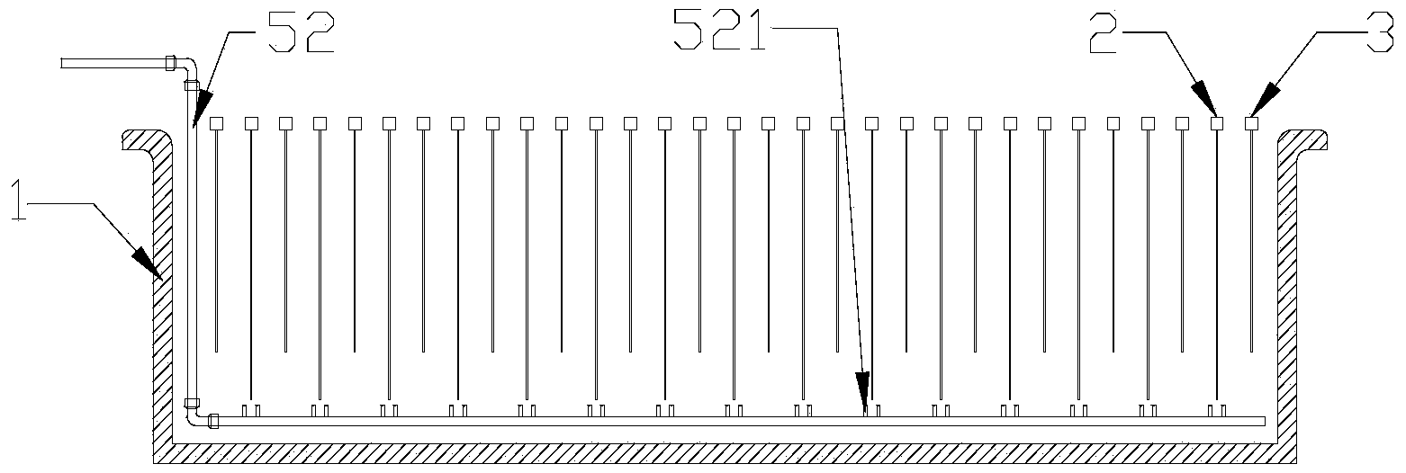
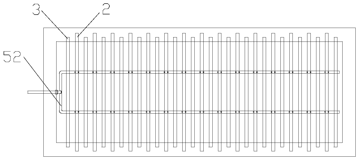
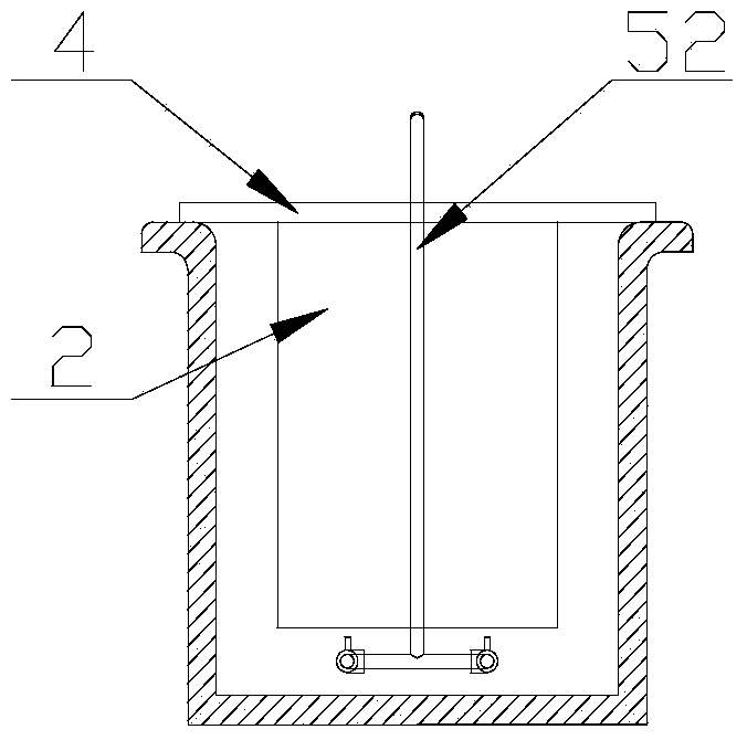
[0025] Warm the copper sulfate solution to 20-60°C, add sulfuric acid to 100-180g / L, turn on the circulation pump 53 in the circulation inflow device 5, so that the catholyte can self-circulate in the electrolytic cell 1, and in each cathode A circulating flow is formed on the surface of the plate 2. When the catholyte self-circulation flow reaches 1500m 3 / Mt, increase the cathode current density to 350A / m 2 , After 4 days of electrolysis, take out the cathode product, the cathode current efficiency reaches 96%, and the output ratio of single-cell cathode product is 200A / m 2 75% increase in time.

Embodiment 2

[0027] Warm the copper sulfate solution to 20-60°C, add sulfuric acid to 100-180g / L, turn on the circulation pump 53 in the circulation inflow device 5, so that the catholyte can self-circulate in the electrolytic cell 1, and in each cathode A circulating flow is formed on the surface of the plate 2. When the catholyte self-circulation flow reaches 1200m 3 / Mt, increase the cathode current density to 300A / m 2 , After 4 days of electrolysis, the cathode product was taken out, the cathode current efficiency reached 98%, and the output ratio of the single-cell cathode product was 200A / m 2 time increased by 50%.

Embodiment 3

[0029] Warm the copper sulfate solution to 20-60°C, add sulfuric acid to 100-180g / L, turn on the circulation pump 53 in the circulation inflow device 5, so that the catholyte can self-circulate in the electrolytic cell 1, and in each cathode A circulating flow is formed on the surface of the plate 2. When the catholyte self-circulation flow reaches 1800m 3 / Mt, increase the cathode current density to 400A / m 2 , after 4 days of electrolysis, take out the cathode product, the cathode current efficiency reaches 95.5%, and the output ratio of single-cell cathode product is 200A / m 2 100% increase.


PUM


Abstract

The invention relates to a high-current density metal electrolytic deposition device with bottom inlet liquid circulation and a realization method thereof. The device comprises an electrolytic tank, cathode plates and anode plates, wherein conducting rods are arranged on the cathode plates and the anode plates; the cathode plates and the anode plates are accommodated in the electrolytic tank; a circulating flow liquid inlet device is mounted at the bottom of the electrolytic tank, and comprises a circulating tank, a solution circulating channel, a circulating pump, a lower tank and an overhead tank; the lower tank and the overhead tank are connected through an extraction-reverse extraction system; the lower tank is connected with one end of the circulating tank through an overflow pipe; and the overhead tank is connected with the other end of the circulating tank through a pipe to form circulation. The device has the following benefits: the device accelerates the migration speed of metal cation through increasing the circulating flow of catholyte to eliminate the cathode concentration polarization and to realize higher cathode current efficiency and high-quality cathode products under the condition of high cathode current density, so that the purpose of prominently improving the production capacity of unit electrolysis devices is achieved through largely increasing the current density.

Description

technical field [0001] The invention relates to the field of electrolytic deposition of metals in insoluble anodes, and mainly relates to a device and a realization method for electrolytic deposition of metals with high current density and high current density at the bottom. Background technique [0002] At present, the traditional electrolytic deposition technology is to place the cathode and anode in the tank where the electrolyte flows slowly. Under the action of the electric field, the anions move to the anode directionally, and the cations move toward the cathode directionally. By controlling certain technical conditions, the target metal cations in The cathode is electrolytically deposited to obtain high-purity electrolytic products. Since the electrode reaction speed is often faster than the ion diffusion speed, concentration polarization is formed. In the traditional electrowinning cell, it is precisely because of the concentration polarization of the cathode that a...

Claims


Application Information

Patent Timeline
IPC IPC(8): C25C7/00C25C7/06C25C1/12
CPCY02P10/20
Inventor 林建平林建灶柳彦石文堂
Owner HANGZHOU SANAL ENVIRONMENTAL TECH
Why Eureka
Try Eureka