Vibration Elimination Equipment for Steam Condensate Pipeline

A steam condensation and vibration elimination technology, applied in the direction of mechanical equipment, pipe components, pipes/pipe joints/fittings, etc., can solve problems such as hidden dangers of pipeline safety operation, achieve good mixing effect, reduce the effect of velocity gradient and quality gradient

Active Publication Date: 2016-01-20
LUXI CHEM GRP
View PDF5 Cites 0 Cited by
  • Summary
  • Abstract
  • Description
  • Claims
  • Application Information

AI Technical Summary

Problems solved by technology

The continuous vibration of the pipeline has caused great hidden dangers to the safe operation of the pipeline

Method used


Image

  • Vibration Elimination Equipment for Steam Condensate Pipeline
  • Vibration Elimination Equipment for Steam Condensate Pipeline
  • Vibration Elimination Equipment for Steam Condensate Pipeline

Examples


Embodiment Construction

[0017] The present invention is described in detail below in conjunction with accompanying drawing:

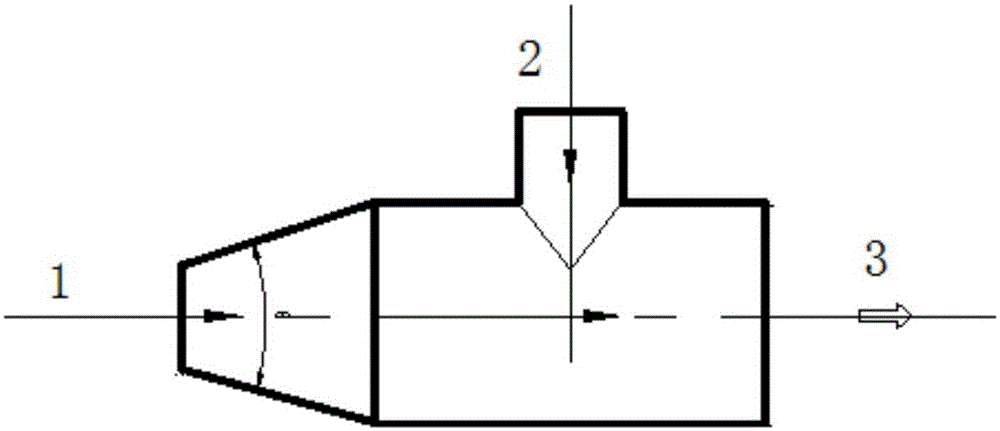
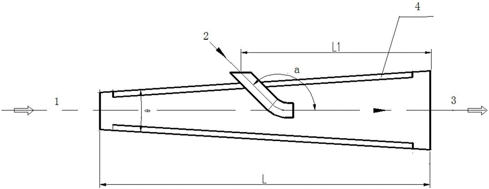
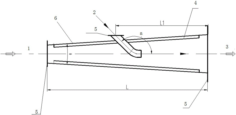
[0018] A steam condensate pipe vibration elimination device, including a tapered pipe 6, the inner surface of the tapered pipe 6 is evenly provided with N pieces of guide plates 4 radially symmetrically distributed along the pipe circumference; and the small diameter of the tapered pipe The end is connected to the condensate I1, and an elbow for connecting the condensate II is inserted obliquely on the conical pipe. The output end of the elbow is the same as the medium flow direction of the condensate I1 and condensate II in the conical pipe; the conical The large-diameter end of the pipeline is the medium outlet 3 where the condensate I1 and the condensate II2 are collected. The elimination equipment is used to install at the confluence pipeline of steam condensate at different pressures and temperatures, so that different fluids can be fully mixed in the same flow state to e...


PUM


Abstract

The invention discloses steam condensate pipeline vibration eliminating equipment which comprises a conical pipeline. N guide plates which are radially symmetrically distributed along the circumference of the pipeline are uniformly arranged on the inner surface of the conical pipeline. The steam condensate pipeline vibration eliminating equipment has the advantages that liquid which flows through the pipeline is regularly and radially mixed by the guide plates, the thickness of laminar flow at a pipe wall of the pipeline is reduced, the liquid of the laminar flow at the pipe wall is changed, vortex formed on the surface of the pipe wall can be effectively broken, flow paths have certain geometric shapes, and optional random mixing can be prevented; a small-diameter end of the conical pipeline is communicated with condensates I, an elbow which is used for being communicated with condensates II is obliquely inserted in the conical pipeline, the direction of an output end of the elbow is identical to a flow direction of media which are formed after the condensates I in the conical pipeline and the condensates II are gathered, liquid of the condensates II flows along the axial direction of a medium pipeline and can flow out in a form identical to a flow state of a header pipe, change of the internal flow state of the header pipe can be eliminated, and steam and liquid phase state conversion can be prevented; a medium outlet for the media which are formed after the condensates I and the condensates II are gathered is formed in a large-diameter end of the conical pipeline.

Description

technical field [0001] The invention relates to the field of steam condensate pipeline vibration elimination equipment, and in particular relates to the problem of pipeline vibration after the same medium is mixed at different temperatures. Background technique [0002] Due to the difference in pressure and temperature when recovering steam condensate in different fields, the excess internal energy of the high-temperature condensate at the collecting pipe is nowhere to be consumed due to the drop in pressure and temperature, and part of the water will inevitably flash and produce short-term vaporization. Or when the flow rate changes, due to the small inertial density of the vapor phase, large bubbles will converge into large bubbles, and the gas will blow to the low-pressure area, causing the bubbles to burst and produce water hammer, which is manifested as the vibration of the condensate main pipe. The continuous vibration of the pipeline has caused great hidden dangers to...

Claims


Application Information

Patent Timeline
Patent Type & Authority Patents(China)
IPC IPC(8): F16L55/045
CPCF16L55/041F16L55/045
Inventor 张文陈运锋刘吉祥刘福青
Owner LUXI CHEM GRP
Why Eureka
Try Eureka