
Front fog lamp and daytime driving lamp combined lamp

A technology for daytime running lights and front fog lights, which is applied in the direction of motor vehicles, road vehicles, cooling/heating devices of lighting devices, etc., can solve the problems of reducing the luminous intensity of LEDs, affecting the service life of LEDs, and limited rear space. , to achieve the effect of reliable quality, saving heat dissipation space, and simple assembly

Inactive Publication Date: 2014-09-10
徐林虎
View PDF0 Cites 2 Cited by
  • Summary
  • Abstract
  • Description
  • Claims
  • Application Information

AI Technical Summary

Problems solved by technology

However, as a car front lamp, its power is relatively large, and the heat generated is very high. At present, the main bulbs used in the front fog lamps on the market are H3 and H1, mainly because the cost of these two bulbs is relatively low; the power of H1 and H3 bulbs is 24V. 70W, 12V is 55W, the power is relatively large, and the heat generated is relatively high, so that the rear of the combined lamp is required to have enough space for heat dissipation, and the volume of the lamp will increase, but the rear space reserved for the lamp by the car is currently limited , it is difficult for the lamp to achieve the minimum volume required for heat dissipation, which makes the design of the lamp difficult; in addition, when the daytime running lamp uses LED as the light source, it is particularly sensitive to the temperature inside the lamp. When the running lights are combined, the temperature of the internal space of the lamps will be greatly increased after the front fog lights are lit, which will greatly affect the service life of the LEDs, and will also reduce the luminous intensity of the LEDs or even fail to meet the requirements of the national standard, which will bring great harm to the driver. Inconvenience

Method used


Image

  • Front fog lamp and daytime driving lamp combined lamp

Examples


Embodiment Construction

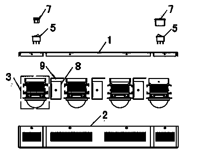
[0010] Depend on figure 1 It is known that a front fog lamp with daytime running lights combined lamp is composed of an upper cover 1, a lower cover 2, a light source cooling module 3, a fan 4, a switch 5, a power plug connection port, a power socket 7 and a power supply 8, Six groups of light source cooling modules 3 are arranged between the upper cover 1 and the lower cover 2, and a power supply box 9 is arranged between two adjacent groups of light source cooling modules 3, and each group of light source cooling modules is composed of a radiator 3- 1. Composed of integrated light source 3-2, focusing cup 3-3, sealing ring 3-4 and convex lens LED module 3-5, fan 4, switch 5, power plug connection port and power socket 7 are located at the bottom of the lower cover 2 Each convex lens module 3 is inlaid on the top of the upper cover 1, the integrated light source 3-2 and the focusing cup 3-3 are fixed on the bottom of the convex lens module 3-5 through the sealing ring 3-4, an...


PUM


Abstract

A front fog lamp and daytime driving lamp combined lamp is composed of an upper cover, a lower cover, multiple sets of light source radiating modules, a fan, a switch, a power source plug wiring port and a power source socket. The light source radiating modules are arranged between the upper cover and the lower cover, and a power source box is arranged between each two adjacent light source radiating modules. The front fog lamp and daytime driving lamp combined lamp is characterized in that each convex lens module is embedded on the upper cover, an integrated light source and a light condensing cup are fixed at the bottom of each convex lens module through a sealing ring, a radiator is arranged on each integrated light source, and a fan is arranged on each radiator. The front fog lamp and daytime driving lamp combined lamp is simple in assembly, firm in mounting and connecting and reliable in quality, and rear-portion radiating space of the lamp is saved greatly; firmness in mounting and connecting is realized, and a wire harness inside the lamp is placed orderly, so that hidden on-fire trouble caused by the fact that the wire harness contacts with a bulb seat is prevented better.

Description

technical field [0001] The invention relates to the automotive lighting industry, in particular to a combined lighting fixture with a front fog lamp and a daytime running lamp. Background technique [0002] The function of front fog lights for automobiles is mainly to effectively improve the driver's visibility in rainy and foggy weather with low visibility. With the implementation of daytime running lights by the European Economic Commission, more and more automobile manufacturers require lamps to provide daytime running lights to meet the needs of the market and safety; According to the requirements of car styling, the front fog lights and daytime running lights will be combined. However, as a car front lamp, its power is relatively large, and the heat generated is very high. At present, the main bulbs used in the front fog lamps on the market are H3 and H1, mainly because the cost of these two bulbs is relatively low; the power of H1 and H3 bulbs is 24V. 70W, 12V is 55W...

Claims


Application Information

Patent Timeline
IPC IPC(8): F21S8/12F21V17/00F21V23/00F21V29/02F21W101/02F21W101/10F21Y101/02F21W107/10F21Y115/10
Inventor 徐林虎
Owner 徐林虎
Learn More