Optical sensing key, touch screen, fingerprint collecting device and electronic device
A technology of electronic equipment and touch screen, applied in the fields of optical sensor keys, touch screen, fingerprint collection equipment, and electronic equipment, can solve the problem that it is difficult to meet the ultra-thin development trend of optical fingerprint collection equipment, the high cost of optical fingerprint collection equipment, the existence of sensitivity and False response and other problems, to achieve the effect of not easy false response, easy maintenance and cleaning, and reducing the number of parts
- Summary
- Abstract
- Description
- Claims
- Application Information
AI Technical Summary
Problems solved by technology
Method used
Image
Examples
Embodiment 1
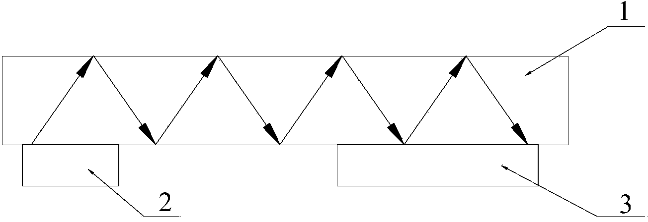
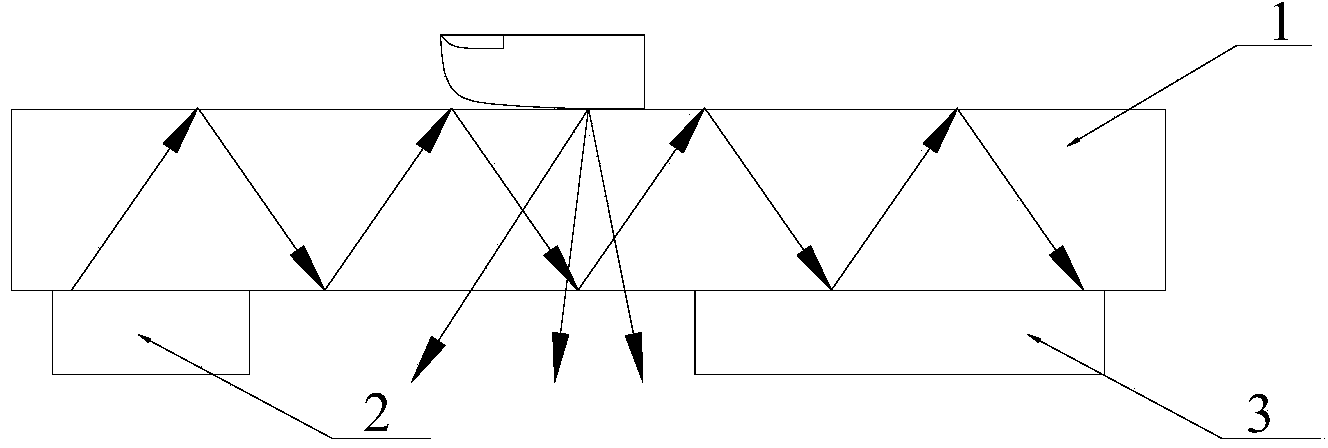
[0053] Such as Figures 1 to 2 As shown, the optical sensor key of this embodiment includes a light guide plate 1, the entire surface of the light guide plate is divided into a propagation area, and a light emitter 2 and a light receiver 3 are respectively arranged under the light guide plate. There is a certain distance between the emitter and the light receiver, and the propagation area, the light emitter and the light receiver form an inductive key. The total reflection transmission is set in the transmission area, the light emitted by the transmitter is transmitted by total reflection in the transmission area, and the light receiver is closely attached to the light guide plate.
[0054] The working principle of the optical sensor key described in this embodiment: the light transmitter turns on the output light, and the light is transmitted through total reflection in the propagation area until it reaches the bonding position of the light receiver and the light guide plate,...
Embodiment 2
[0058] Such as image 3 As shown, the optical sensor key of this embodiment includes a light guide plate 1, the entire surface of the light guide plate is a propagation area, and a light emitter 2 is arranged on one side of the end face of the light guide plate, and a light guide plate is set on the light guide plate at the same time. A light receiver 3 is arranged on the other side corresponding to one side of the end face of the transmitter, and the propagation area, the light transmitter and the light receiver form an induction key. In this embodiment, the incident angle of the light emitted by the light emitter is based on the fact that it can be fully emitted in the light guide plate, the light emitted by the emitter is transmitted through total reflection in the propagation area, and the light receiver is closely attached to the guide plate. Light board set.
[0059] The difference between this embodiment and Embodiment 1 lies in that the installation positions of the l...
Embodiment 3
[0063] Such as Figures 4 to 5 As shown, the optical sensor key in this embodiment at least includes a light guide plate 1, and the light guide plate has a plurality of propagation areas, and each propagation area corresponds to a pair of light emitters 2 and light receivers 3 arranged at intervals, and each propagation area corresponds to The light emitter and the light receiver are arranged below the propagation area, the propagation area and its corresponding pair of light emitters and light receivers form an induction key 11a, 11b, 11c, and the light output by each pair of light emitters can be And it can only propagate in the light propagation area corresponding to the light emitter, and the light receivers in each pair receive the light output from the corresponding propagation area.
[0064] In this embodiment, since each propagation area corresponds to a pair of optical transmitters and optical receivers, the working principle of each pair of optical transmitters and o...
PUM
 Abstract
Description
Claims
Application Information
 - R&D
- Intellectual Property
- Life Sciences
- Materials
- Tech Scout
- Unparalleled Data Quality
- Higher Quality Content
- 60% Fewer Hallucinations
Browse by: Latest US Patents, China's latest patents, Technical Efficacy Thesaurus, Application Domain, Technology Topic, Popular Technical Reports.
© 2025 PatSnap. All rights reserved.Legal|Privacy policy|Modern Slavery Act Transparency Statement|Sitemap|About US| Contact US: help@patsnap.com


