Arrangement structure of handle seat and transmission box of a portable tillage machine

A technology of layout structure and handle seat, which is applied in the field of micro tillage machines, can solve the problems of complicated installation process of worm transmission box, poor reliability of handle seat connection, unfavorable miniaturization of micro tillage machines, etc. Reliable, easy to overcome obstacles, compact structure effect

Active Publication Date: 2016-03-02
CHONGQING JIAMU MACHINERY
View PDF6 Cites 0 Cited by
  • Summary
  • Abstract
  • Description
  • Claims
  • Application Information

AI Technical Summary

Problems solved by technology

The existing micro-tiller frame not only has complex structure, difficult processing and high production cost, but also takes up a lot of space, which will increase the volume of the entire micro-tiller, which is not conducive to the development of micro-tillers in the direction of miniaturization
[0004] The handle on the tiller is generally composed of a handle tube and a handle seat, and the handle tube and the handle seat are usually in one structure, so that the space is large and will increase the cost of packaging and transportation; at the same time, the handle seat is connected on the frame The reliability is poor, and the disassembly operation is inconvenient
[0005] The powertrain on the tiller is usually a vertical engine, and the screw transmission box is installed vertically accordingly. On the one hand, the installation process of the worm transmission box is relatively complicated and the reliability is poor; on the other hand, the worm transmission box is installed in the The rack takes up a lot of space, which will also increase the volume of the whole tiller

Method used


Image

  • Arrangement structure of handle seat and transmission box of a portable tillage machine
  • Arrangement structure of handle seat and transmission box of a portable tillage machine
  • Arrangement structure of handle seat and transmission box of a portable tillage machine

Examples


Embodiment Construction

[0026] Below in conjunction with accompanying drawing and embodiment the present invention will be further described:

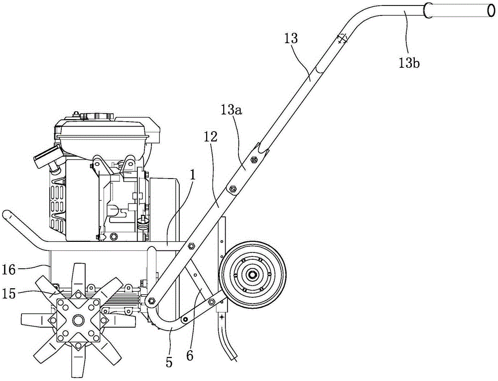
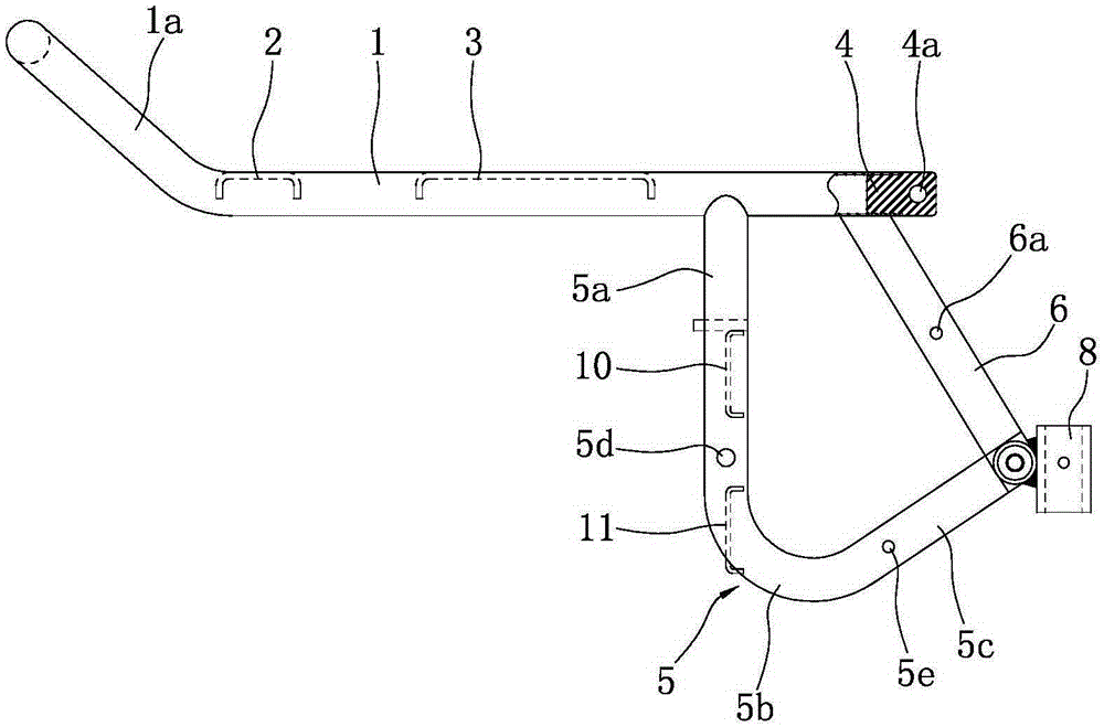
[0027] like figure 1 , image 3 , Figure 4 , Figure 5 As shown, the frame consists of a main pipe 1, a beam 2, a supporting plate 3, a plug 4, an elbow 5, an inclined pipe 6, a horizontal pipe 7, a positioning sleeve 8, a stopper 9, an upper positioning plate 10 and a lower positioning plate 11, etc. constitute. Wherein, the main pipe 1 is in a "U" shape with the front end closed and the rear end open, and the front end of the main pipe 1 is tilted up to form a bumper 1a. Except for the bumper 1a, the remaining part of the main pipe 1 is a horizontal section symmetrically arranged on the left and right sides, and the bumper 1a and the horizontal section of the main pipe 1 have an included angle of 130-150°. A crossbeam 2 is arranged at the front between the two horizontal sections of the main pipe 1. The crossbeam 2 is a rectangular plate structure. B...


PUM


Abstract

The invention discloses a portable handlebar bracket and transmission case arrangement structure of a mini tiller. A transverse beam (2) is fixed to the upper end of a front support (16), the left end and the right end of the bottom of the front support (16) are connected with the top of the front end of a screw transmission case (15) through bolts, elbows (5) are in the shape of V, a first straight segment (5a), an arc transition segment (5b) and a second straight segment (5c) are connected in sequence to form each elbow, lower handlebar bracket installing holes (5d) are formed in the lower portions of the first straight segments (5a), and bolts penetrate through the lower handlebar bracket installing holes (5d) and assembling holes, in the corresponding sides, in the lower end of a handlebar bracket (12) so that the elbows (5) and the handlebar bracket (12) can be connected together. The portable handlebar bracket and transmission case arrangement structure of the mini tiller is simple in modeling, compact in structure and small in size, the handlebar bracket and handlebar tubes forming a handlebar are of a split structure, and can be conveniently and rapidly disassembled and assembled, and the packaging and transportation cost can be effectively reduced; the screw transmission case is installed horizontally, the size of the mini tiller can be further reduced, and the screw transmission case is firm and reliable in installation, and good in stability.

Description

technical field [0001] The invention belongs to the technical field of tillage machines, and in particular relates to the arrangement structure of a handle seat and a transmission box on a tillage machine. Background technique [0002] Micro tillage machine is an agricultural tool in the new era. It has the characteristics of light weight, small size and simple structure. It is widely used in dry land, paddy fields, orchards, etc. in plains, mountains, and hills. , spraying and other operations, it can also be towed by a trailer for short-distance transportation. The micro tillage machine has strong flexibility, can drive freely in the field, is convenient for users to use and store, saves the trouble of large agricultural machinery not being able to enter the mountainous fields, and saves farmers a lot of time in the busy season. [0003] The frame is an important part of the tiller, and it is the skeleton of the tiller, which is used to arrange the powertrain, blade, hand...

Claims


Application Information

Patent Timeline
Patent Type & Authority Patents(China)
IPC IPC(8): A01B51/02A01B71/02
Inventor 邵海波向安林
Owner CHONGQING JIAMU MACHINERY
Why Eureka
Try Eureka