Stirring impeller

A technology of stirring impeller and stirring blade, which is applied in the directions of mixer accessories, dissolving, mixer, etc., can solve the problems of laborious removal of blades, reduce work efficiency, increase labor intensity, etc., so as to reduce labor intensity, increase work efficiency and structure. simple effect

Inactive Publication Date: 2014-09-17
安徽省神洲建材科技有限公司
View PDF5 Cites 5 Cited by
  • Summary
  • Abstract
  • Description
  • Claims
  • Application Information

AI Technical Summary

Problems solved by technology

The stirring impeller of this structure is easy to break due to the welding part, so it can only be used in low-viscosity, low-strength working environment, otherwise it

Method used


Image

  • Stirring impeller
  • Stirring impeller
  • Stirring impeller

Examples


Embodiment Construction

[0010] The present invention will be further described below in conjunction with accompanying drawing:

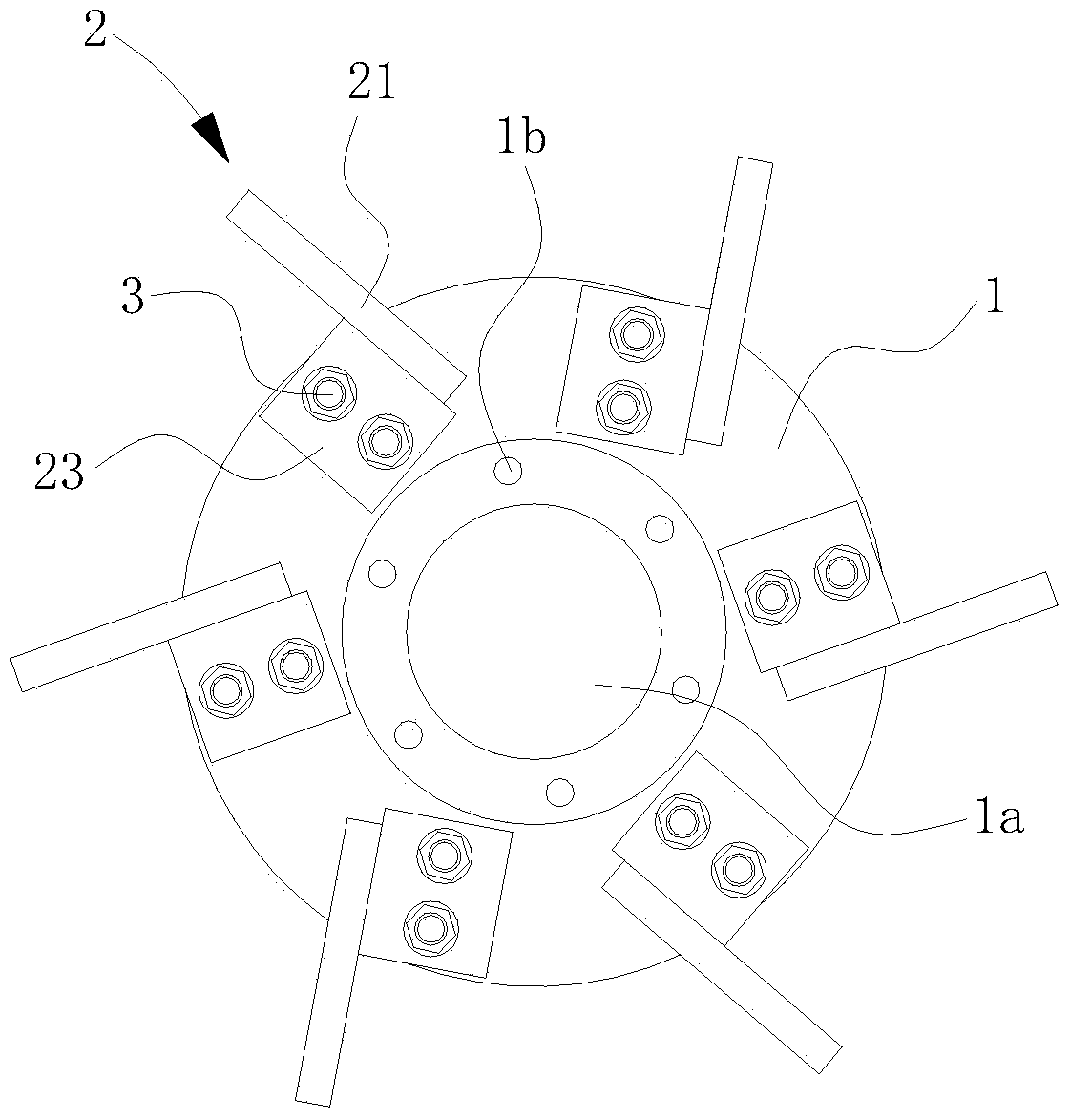
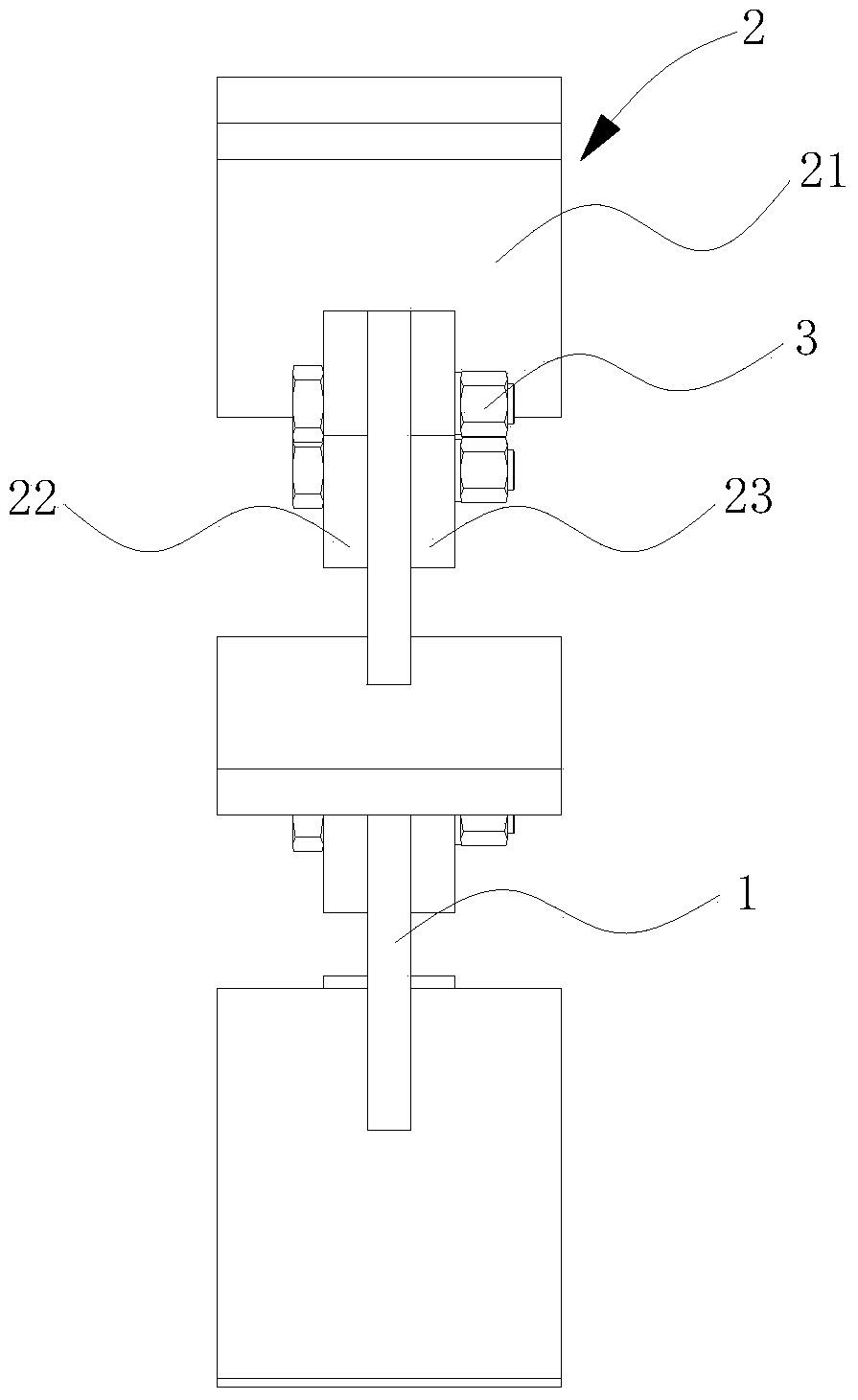
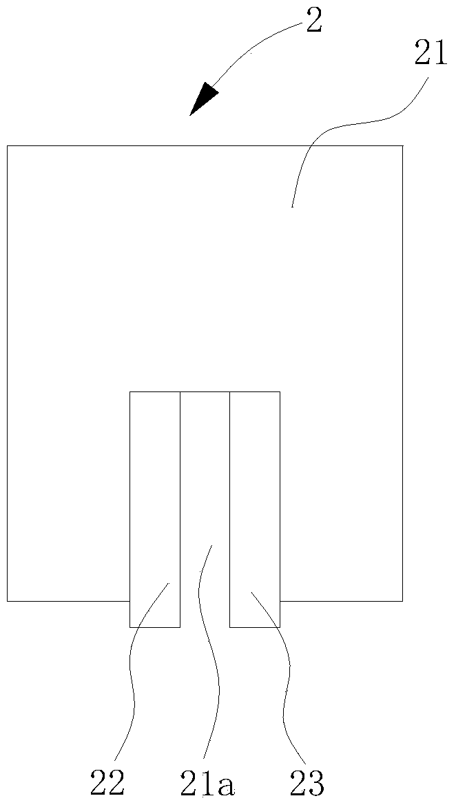
[0011] see figure 1 , 2 and 3.

[0012] The stirring blade provided by the present invention includes a wheel disc 1 and more than two stirring blades 2, the center of the wheel disc 1 is provided with an installation through hole 1a, and the periphery of the installation through hole 1a is provided with a number of fixed through holes 1b, and the two or more stirring blades 2 Evenly installed on the outer edge of the wheel disc 1, the stirring blade 2 includes a rectangular paddle 21, which has a strip-shaped through groove 21a with one end closed and the other end open. The center lines of the center lines are coaxial, the width of the strip-shaped through groove 21a corresponds to the thickness of the wheel disc 1, and the rectangular paddle 21 is provided with a first fixing plate 22 on the left side of the strip-shaped through groove 21a, and a second fixing plate on...


PUM


Abstract

The invention discloses a stirring impeller. The stirring impeller comprises a wheel disc and at least two stirring blades uniformly mounted at the edge of the wheel disc, wherein the stirring blades comprise rectangular paddles, strip-shaped through troughs are formed in the rectangular paddles, one ends of the strip-shaped through troughs are closed, and the other ends of the strip-shaped through troughs are open; first fixed plates are arranged on the left sides of the strip-shaped through troughs in the rectangular paddles, second fixed plates are arranged on the right sides of the strip-shaped through troughs in the rectangular paddles, and the first fixed plates and the right fixed plates are vertical to the rectangular paddles; the stirring blades are mounted at the edge of the wheel disc by virtue of at least two bolts penetrating through the first fixed plates, the wheel disc and the second fixed plates. According to the stirring impeller, the stirring blades are fixed on the wheel disc by virtue of the bolts, and the stirring impeller in the structure is difficult to break, is firmer than a welded stirring impeller, so that the stirring blades can bear a large stirring force; when the stirring blades are damaged and need to be replaced, the stirring blades can be easily detached and replaced only by detaching the bolts, so that the working efficiency is improved, and the labor intensity is reduced.

Description

technical field [0001] The invention relates to the field of stirring equipment, in particular to a stirring impeller. Background technique [0002] At present, many industries such as chemical industry and building materials need to use mixing equipment. One of the main components of mixing equipment, the mixing impeller has paddle type, curved blade turbine type, folded blade turbine type, disc turbine type, pusher type, etc. form. The existing paddle-type stirring impeller includes a wheel disc and a stirring blade group. The center of the wheel disc is provided with an installation through hole, and a number of fixed through holes are arranged on the periphery of the installation through hole. The stirring blade group includes more than two stirring blades. Evenly installed on the outer edge of the wheel, the stirring blades include rectangular paddles, which have a through groove with one end closed and the other end extending to the edge, the through groove is coa...

Claims


Application Information

Patent Timeline
IPC IPC(8): B01F15/00
Inventor 胡增坤胡学斌陈敬荣
Owner 安徽省神洲建材科技有限公司
Why Eureka
Try Eureka