Large engine crankshaft CNC grinding machine

A CNC grinding machine and engine technology, applied in the direction of grinding machines, parts of grinding machine tools, and machine tools designed for grinding the rotating surface of workpieces, etc., can solve the problems of long turnaround time, low precision, unstable quality, etc., and achieve reliable product quality Guarantee, stable operation of equipment, and the effect of improving production efficiency

Active Publication Date: 2016-07-27
湖北伟翔数控机床股份有限公司
View PDF5 Cites 0 Cited by
  • Summary
  • Abstract
  • Description
  • Claims
  • Application Information

AI Technical Summary

Problems solved by technology

[0002] The existing large-scale crankshaft grinding process is generally semi-manual processing, because this processing process takes up a considerable part of the time period, and at the same time, the investment in grinding equipment and the large area occupied by the site affect the grinding process efficiency and product quality. The process conversion is complicated, the turnaround time is long, and the clamping method of the spindle head end chassis makes the crankshaft easy to deviate from the center position, resulting in unstable quality, low precision and low efficiency

Method used


Image

  • Large engine crankshaft CNC grinding machine
  • Large engine crankshaft CNC grinding machine
  • Large engine crankshaft CNC grinding machine

Examples


Embodiment Construction

[0024] The present invention will be further described in detail below in conjunction with the accompanying drawings and specific embodiments to facilitate a clear understanding of the present invention, but they do not limit the present invention.

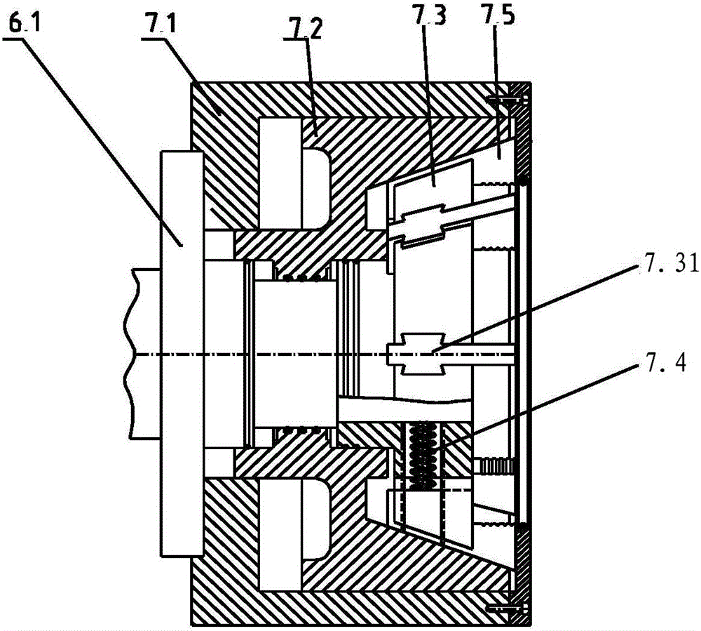
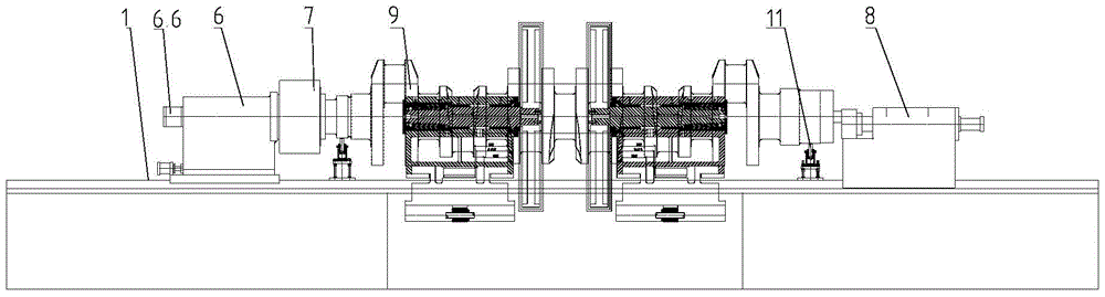
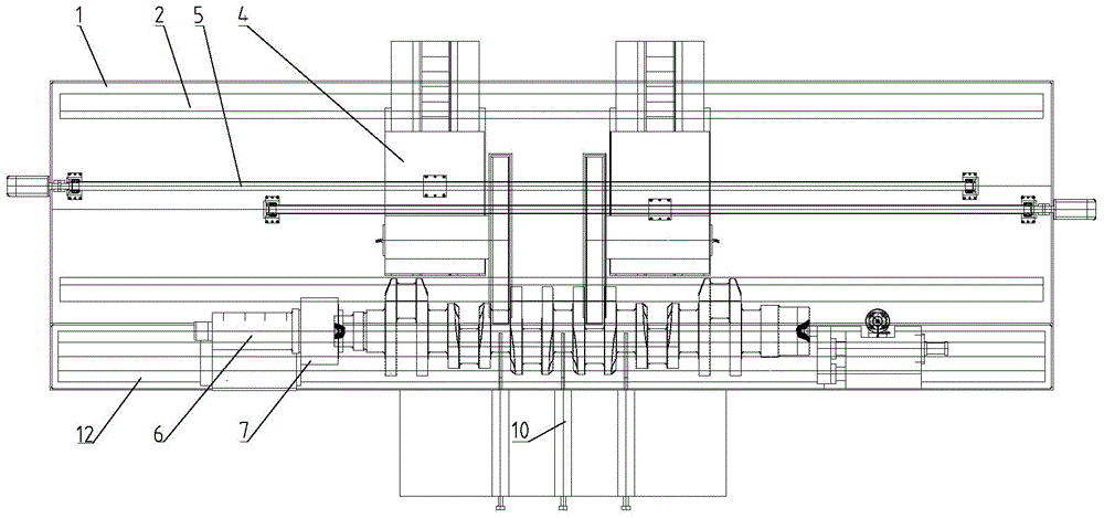
[0025] Such as figure 1 — Figure 5 As shown, the present invention includes a main frame 1, the main frame 1 is provided with a grinder axially moving guide rail 2, and an axially moving bracket 3 is slidably connected to the grinder axially moving guide rail 2, and the axially A grinder assembly 4 is slidably connected to the moving bracket 3; a main rail 12 is provided on the main frame 1, and a main shaft head end mechanism 6 and a main shaft tail end mechanism 8 are slidably connected to the main frame 12, and the main shaft The bottom end of the head-end mechanism 6 is connected with a first driving device 6.8. The spindle head-end mechanism 6 includes a spindle housing 6.7 and a spindle 6.1 installed inside the spindle hou...


PUM


Abstract

The invention relates to a numerically controlled large engine crankshaft grinder, which comprises a main bed, an axial grinding machine movement track is arranged on the main bed, an axial moving carriage is slidably connected with the axial grinding machine movement track, and a grinding machine assembly is slidably connected with the axial moving carriage; a main track is arranged on the main bed, a spindle head mechanism and a spindle tail mechanism are slidably connected with the main track, a first driver is connected with the bottom of the spindle head mechanism, the spindle head mechanism comprises a spindle box and a spindle mounted in the spindle box, a fixture mechanism is fixed on the front end of the spindle, an oil distributor is fixed on the rear end of the spindle, a motor rotor and a motor stator which cooperate with each other and are arranged in the spindle box are sleeved on the spindle, and the center of the front end of the spindle is provided with a centre. The numerically controlled large engine crankshaft grinder increases production efficiency, and provides a reliable guarantee for product quality.

Description

technical field [0001] The invention relates to an engine crankshaft grinder, in particular to a large-scale engine crankshaft numerical control grinder. Background technique [0002] The existing large-scale crankshaft grinding process is generally semi-manual processing, because this processing process takes up a considerable part of the time period, and at the same time, the investment in grinding equipment and the large area occupied by the site affect the grinding process efficiency and product quality. The process conversion is complicated, the turnaround time is long, and the clamping method of the spindle head end chassis makes the crankshaft easy to deviate from the center position, resulting in unstable quality, low precision and low efficiency. Contents of the invention [0003] The purpose of the present invention is exactly to provide a kind of large-scale engine crankshaft numerical control grinder for the defective of prior art. [0004] The technical solut...

Claims


Application Information

Patent Timeline
Patent Type & Authority Patents(China)
IPC IPC(8): B24B5/42
CPCB24B5/42B24B41/061B24B41/065B24B47/16
Inventor 冯英华
Owner 湖北伟翔数控机床股份有限公司
Why Eureka
Try Eureka