Mini roller press

A technology of roller presses and miniature rollers, which is applied in the direction of presses, material forming presses, manufacturing tools, etc., which can solve the problems of larger device size, increased installation area, and equipment operation failures, and achieve simple maintenance operations, Effect of reducing device failure and large load capacity

A technology of roller presses and miniature rollers, which is applied in the direction of presses, material forming presses, manufacturing tools, etc., which can solve the problems of larger device size, increased installation area, and equipment operation failures, and achieve simple maintenance operations, Effect of reducing device failure and large load capacity

CN104044293AActive Publication Date: 2014-09-17KOREA ATOMIC ENERGY RES INST

Image

  • Mini roller press
  • Mini roller press
  • Mini roller press

Examples


Embodiment Construction

[0052] Next, the micro-roller according to the present invention will be described in more detail with reference to the accompanying drawings.

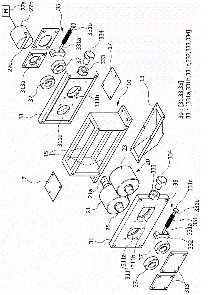
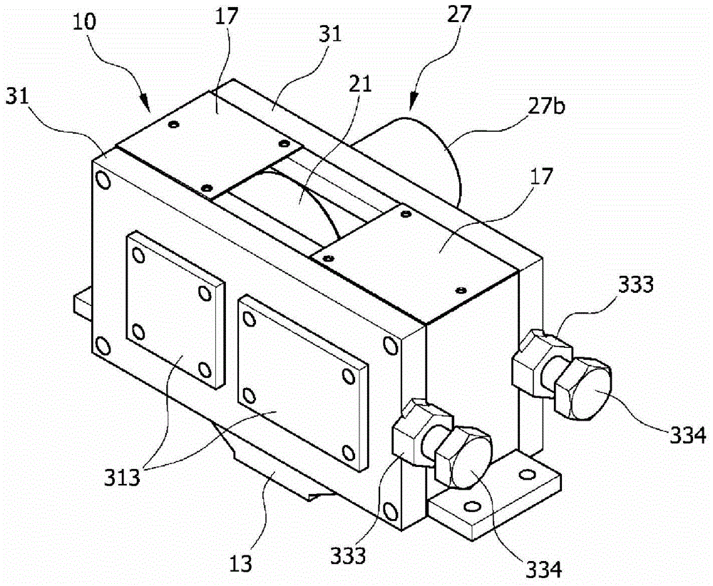
[0053] Such as Figure 1 to Figure 3 As shown, the micro-roller according to the present invention includes: a housing 10 ; a forming roll module 20 for pressurizing the loaded powder; and a rolling device 30 for pressing the cylinder of the forming roll module 20 .

[0054] Such as Figure 1 to Figure 3 As shown, the outer cover 10 according to the present invention is provided with split parts 15 on the upper, lower, front and rear sides, and the two sides of the upper split part 15 are connected with cover plates 17 in a spaced manner.

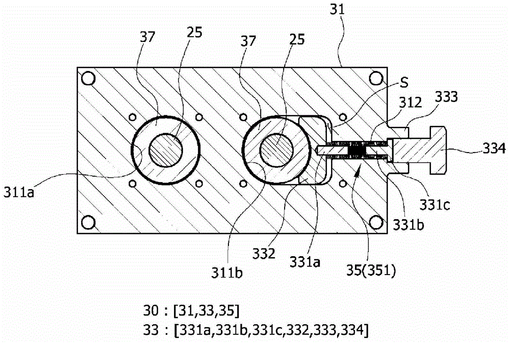
[0055] Such as Figure 4 As shown, the space between the cover plates 17 is connected to the input port 11, that is, the hopper, and the powder P or powder (hereinafter referred to as "powder") of the used nuclear fuel or radioactive waste is loaded into the inside of the outer cover 10. Forming...


PUM


Abstract

The invention relates to a mini roller press. To be particular, the roller press comprises: a housing (10) with a charge port (11) and a discharge port (13); a forming roller module (20) comprising a driving cylinder (21) placed in the housing (10) and used for compression forming of powder loaded via the charge port (11) and a driven cylinder (23) forming a pair with the driving cylinder (21); and a roll pressing device (30) which conducts pressure adjustment of the cylinders of the forming roller module (20) in case the load applied to the cylinders is too large so as to guide a part of or the whole displacement of the cylinders.

Description

technical field [0001] The present invention is as a kind of roller pressing device that puts used nuclear fuel or radioactive waste and other powders or powders and ordinary powders or powders into a certain size product (or semi-finished product) between rollers, and introduces a plurality of An elastic unit composed of coil springs. That is, the present invention relates to a micro-rolling machine. By arranging coil springs in the device, not only can the device become more compact, but also because there is no need to configure auxiliary equipment for the rolling device, it can be used even in a narrow room such as a hot room. It can also be easily set up and operated in the space. Background technique [0002] Korean Patent No. 1998-0008371 (hereinafter referred to as "prior art") discloses a rolling machine driving device, a rolling machine, and a rolling method as a rolling machine and a rolling machine according to the prior art. [0003] In addition, as a similar ...

Claims


Application Information

Patent Timeline
17 Sep 2014
Publication
CN104044293A
IPC
B30B11/16; B30B15/00; B30B15/28
CPC
B30B11/16; B30B15/0005; B30B15/14
Inventors
罗相浩; 李起源