Drain-off device for preventing generation of steam locking favorably

A steam lock and water-repellent technology, applied in the direction of steam traps, mechanical equipment, etc., can solve the problems of unfavorable heat transfer efficiency of heat exchange equipment, safety and reliability of steam pipe network, easy occurrence of steam lock, etc., to achieve simple structure, prevent steam leakage The effect of venting

Inactive Publication Date: 2014-09-17
CHENGDU KELIFU SCI & TECH
View PDF6 Cites 5 Cited by
  • Summary
  • Abstract
  • Description
  • Claims
  • Application Information

AI Technical Summary

Problems solved by technology

[0004] In order to solve the above-mentioned non-condensable gas in the prior art, compared with the thermodynamic steam trap, the steam lock phenomenon is prone to occur at the drain port, which is not conducive to the heat exchange efficiency of the heat exchange equipment and the steam pipe. To solve the problem of safety and reliability of network operation, the present invention provides a water-repellent device that is beneficial to prevent the generation of vapor lock

Method used


Image

  • Drain-off device for preventing generation of steam locking favorably
  • Drain-off device for preventing generation of steam locking favorably

Examples


Embodiment 1

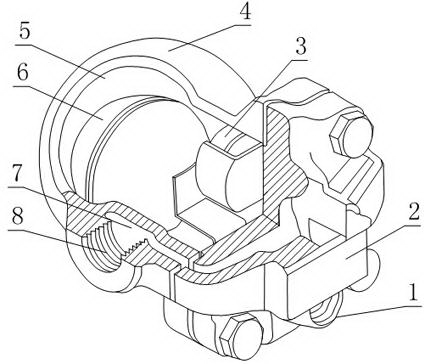
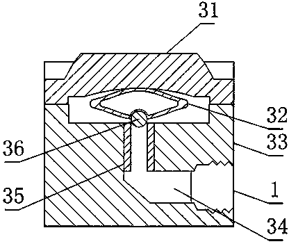
[0022] Such as figure 1 and figure 2 , a kind of drainage device that is beneficial to prevent vapor lock provided by the present invention includes a left valve cover 4 and a right valve cover 2 connected by bolts, a condensed water volume chamber 5 is arranged between the left valve cover 4 and the right valve cover 2, The left valve cover 4 or the right valve cover 2 is provided with an inlet pipe 8 and an outlet pipe 1 connected with the condensed water volume chamber 5, and the condensed water volume chamber 5 is provided with a floating ball 6, and also includes a 5 on the upper side of the evacuation device 4, the evacuation device 4 includes a thermostatic metal sheet 32, a sealing ball 36, and a steam lock discharge flow channel 34 arranged on the left valve cover 4 or the right valve cover 2, the The front and rear ends of the steam lock discharge channel 34 are respectively connected with the condensed water volume chamber 5 and the outlet pipe 1, and the sealing ...

Embodiment 2

[0025] This embodiment is further limited on the basis of embodiment 1: as figure 1 and figure 2 , in order to reduce the possibility that the present invention is blocked by impurities such as rust and welding slag in the pipe network, and prolong the service life of the sealing surface in the present invention, a filter screen groove 7 is also included, and the filter screen groove 7 is arranged on the inlet pipe 8 At any position from the inlet end to the flow path of the condensed water volume chamber 5, the filter screen groove 7 is used for setting the filter screen.

[0026] A seal seat 35 is embedded in the inlet section of the steam lock discharge channel 34, and the material of the seal seat 35 is stainless steel. The provided sealing seat 35 is used to increase the wear resistance of the sealing surface formed by the sealing ball 36 and the steam lock discharge channel 34, which is beneficial to the service life of the present invention.

Embodiment 3

[0028] The present embodiment is further limited on the basis of embodiment 1: as figure 1 and figure 2 , the emptying device 4 also includes an upper cover 31 and a lower cover 33 that are detachably connected, and a sheet metal accommodation cavity is formed between the upper cover 31 and the lower cover 33, and the thermostatic metal sheet 32 ​​is located on the metal sheet. The metal sheet accommodating chamber communicates with the condensed water volume chamber 5 through the labyrinth channel. The set labyrinth flow channel avoids the steam or non-condensable gas entering the present invention from directly colliding with the thermostatic metal sheet 32 ​​through the setting of the flow channel corner.


PUM


Abstract

The invention discloses a drain-off device for preventing generation of steam locking favorably. The drain-off device comprises a left valve deck and a right valve deck. A condensate water accommodation chamber is arranged between the left valve deck and the right valve deck; an inlet tube and an outlet tube are arranged on the left valve deck and the right valve deck; a floating ball is arranged in the condensate water accommodation chamber. The drain-off device also comprises an emptier. The emptier comprises a thermal static metal piece, a sealing ball and a steam locking discharging runner; the front end and the back end of the steam locking discharging runner are connected with the condensate water accommodation chamber and the outlet tube respectively; the sealing ball is fixed on the thermal static metal piece, and directly faces the front end of the steam locking discharging runner; the section of the thermal static metal piece is a diamond; the sealing ball is positioned in the apex angle of the diamond. By applying the drain-off device, automatic discharging of non-condensable gas can be realized, and the service life is long.

Description

technical field [0001] The invention relates to a steam pipe network equipment, in particular to a water-repellent device which is beneficial to prevent the generation of steam lock. Background technique [0002] The function of the steam trap is to discharge the condensed water, air and carbon dioxide gas in the steam system as soon as possible; at the same time, it can prevent the leakage of steam to the greatest extent. There are many kinds of steam traps. On pipelines with high drainage requirements, ball float steam traps are generally used in the prior art, which can ensure that the condensed water in the steam channel can be discharged continuously and in large quantities without being affected by pressure fluctuations and load changes. . [0003] The working principle of the floating ball trap is to connect the floating rod through the floating ball, and control the connection between the condensed water volume chamber and the drain port through the change of the li...

Claims


Application Information

Patent Timeline
Patent Type & Authority Applications(China)
IPC IPC(8): F16T1/20F16T1/38F16T1/45
Inventor 胡明容
Owner CHENGDU KELIFU SCI & TECH
Why Eureka
Try Eureka