Electricity-saving control circuit and electronic equipment

A power-saving control and circuit technology, applied in the electronic field, can solve the problems of cutting off the output voltage, unable to restart the output, power consumption of the chip, etc., and achieve the effect of reducing power consumption

Active Publication Date: 2014-09-17
TENDYRON CORP
View PDF7 Cites 4 Cited by
  • Summary
  • Abstract
  • Description
  • Claims
  • Application Information

AI Technical Summary

Problems solved by technology

However, any low power consumption mode currently only turns off some unused control units, and the chip still consumes power.
[0003] And LDO (Low Drop-Out Regulator, low-dropout linear regulator) is designed in the MCU system to provide a stable and suitable voltage for the operation of the MCU chip. However, in the traditional way of use, the output terminal (Vout) of the LDO can only Provide a stable output voltage, cannot cut off its own output voltage by itself, let alone restart the output under appropriate incentives

Method used


Image

  • Electricity-saving control circuit and electronic equipment
  • Electricity-saving control circuit and electronic equipment
  • Electricity-saving control circuit and electronic equipment

Examples


Embodiment 1

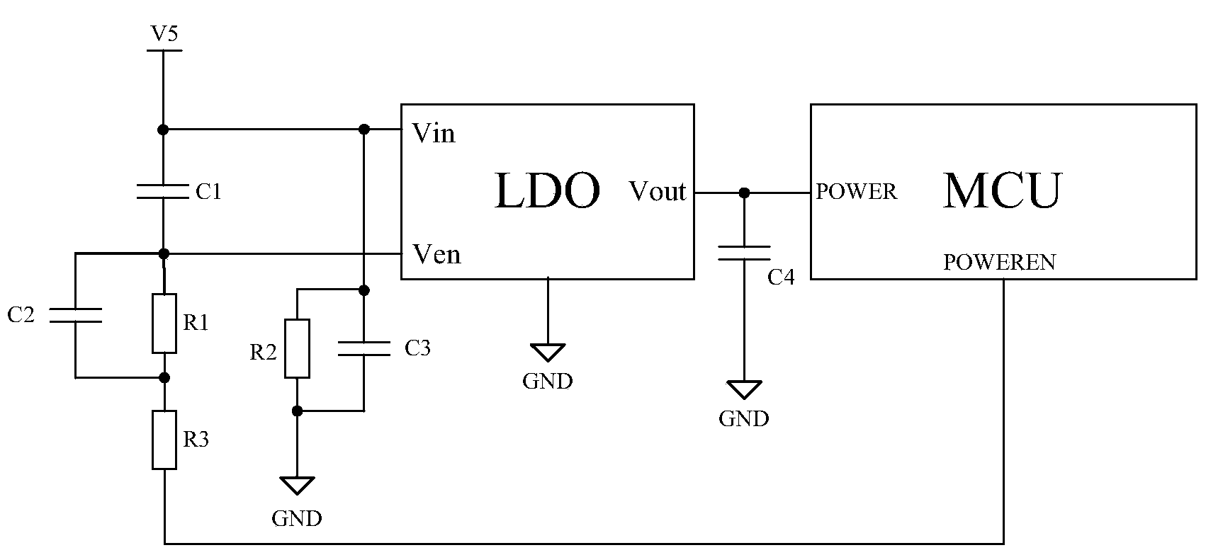
[0046] figure 2 A schematic diagram of the power-saving control circuit provided by Embodiment 1 of the present invention is shown, see figure 2 , the power-saving control circuit of Embodiment 1 of the present invention includes:

[0047] The power supply is connected to the power input pin Vin of the LDO, the power supply is grounded through the third capacitor C3 and the second resistor (protection circuit) R2 connected in parallel, and the power supply is connected to the switch pin Ven of the LDO through the first capacitor (power-on impact capacitor) C1, and the LDO The switch pin Ven is connected to one end of the third resistor (current limiting circuit) R3 through the parallel connection of the second capacitor (anti-shake circuit) C2 and the first resistor (protection circuit) R1, and the third resistor (current limiting circuit) R3 The other end is connected to the control pin MCU-POWEREN of the MCU, the power output pin Vout of the LDO is grounded through the fo...

Embodiment 2

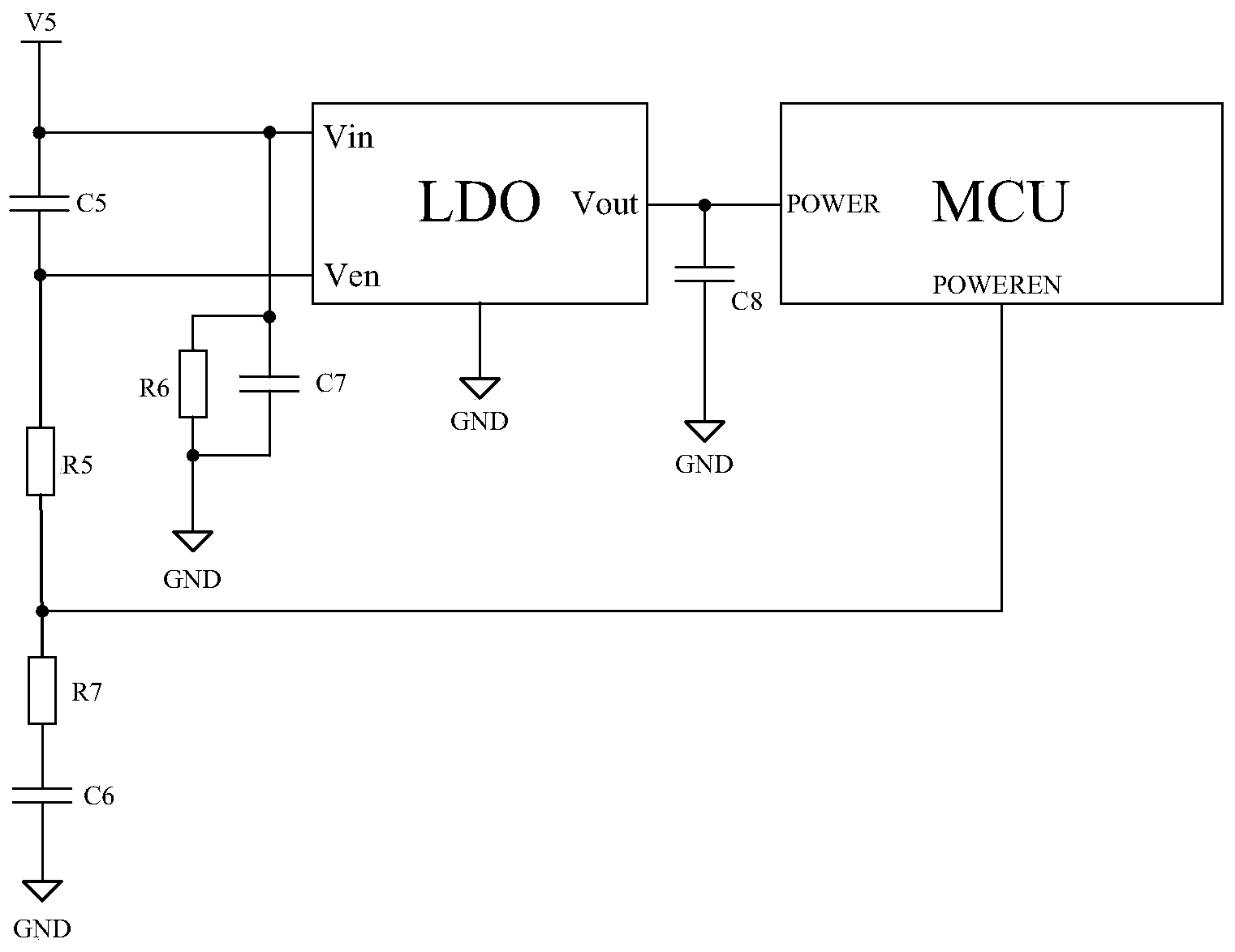
[0049] image 3 A schematic diagram of the power-saving control circuit provided by Embodiment 2 of the present invention is shown, see image 3 , the power-saving control circuit of Embodiment 2 of the present invention includes:

[0050] The power supply is connected to the power input pin Vin of the LDO, the power supply is grounded through the seventh capacitor C7 and the sixth resistor (protection circuit) R6 connected in parallel, and the power supply is connected to the switch pin Ven of the LDO through the fifth capacitor (power-on impact capacitor) C5, and the LDO The switch pin Ven of the MCU is connected to the control pin MCU-POWEREN of the MCU through the fifth resistor (current limiting circuit) R5, and the control pin MCU-POWEREN of the MCU is connected to the seventh resistor (protection circuit) R7 and the sixth capacitor (anti- The dithering circuit) C6 is grounded, the power output pin Vout of the LDO is grounded through the eighth capacitor C8, and the pow...


PUM


Abstract

The invention provides an electricity-saving control circuit and electronic equipment. The electricity-saving control circuit comprises an LDO, a power-on impact capacitor and an MCU, the LDO comprises a power source input pin, a switch pin and a power source output pin, one end of the power-on impact capacitor is connected with the power source input pin, the other end of the power-on impact capacitor is connected with the switch pin, the MCU comprises an MCU power source pin and an MCU control pin, the MCU power source pin is connected with the power source output pin, and the MCU control pin is connected with the switch pin. The MCU is used for being triggered by a preset trigger condition to output low levels to the MCU control pin under a normal mode to enter in an electricity saving mode, and according to the normal mode, the MCU outputs high levels to the MCU control pin. According to the electricity-saving control circuit and the electronic equipment, power consumption can be reduced to the maximum extent when an MCU system with the LDO is in a low power consumption mode, and the electricity consumption is zero when the MCU is idle or does not need to work. The enabling control function of the switch pin of the LDO is utilized, the power supply of the MCU can be powered off automatically, and the power supply can be restarted under proper excitation.

Description

technical field [0001] The invention relates to the field of electronic technology, in particular to a power-saving control circuit and electronic equipment. Background technique [0002] At present, the MCU (Micro Control Unit, micro control unit) chip design process has a low power mode setting, so that the chip can save more power when it is idle. However, in any current low power consumption mode, only some control units that are not in use are turned off, and the chip still consumes power. [0003] And LDO (Low Drop-Out Regulator, low-dropout linear regulator) is designed in the MCU system to provide a stable and suitable voltage for the operation of the MCU chip. However, in the traditional way of use, the output terminal (Vout) of the LDO can only To provide a stable output voltage, it cannot cut off its own output voltage by itself, let alone restart the output under appropriate incentives. [0004] Therefore, how to ensure that the MCU system with LDO minimizes po...

Claims


Application Information

Patent Timeline
IPC IPC(8): G05B19/04
Inventor 李东声
Owner TENDYRON CORP
Why Eureka
Try Eureka