
System identification method based on upper computer and programmable logic controller

A programming controller and system identification technology, applied in electrical program control, comprehensive factory control, comprehensive factory control, etc., can solve problems such as inability to achieve high-speed data acquisition and storage, increase hardware costs, and inability to integrate

Active Publication Date: 2014-09-17
CENT SOUTH UNIV
View PDF3 Cites 2 Cited by
  • Summary
  • Abstract
  • Description
  • Claims
  • Application Information

AI Technical Summary

Problems solved by technology

However, the minimum refresh period of WinCC is only 250ms, and the minimum data archiving period is 500ms, which is far greater than the sampling period of PLC. If it is not developed, it will not be possible to achieve high-speed data collection and storage
At present, in the experimental research of system identification, high-speed acquisition modules such as data acquisition cards and DSP are mostly used, and they are used in conjunction with LABVIEW and other host computer software that are convenient for generating excitation signals, but this undoubtedly increases the hardware cost, and cannot be compared with the original control The system achieves a good integration

Method used


Image

  • System identification method based on upper computer and programmable logic controller
  • System identification method based on upper computer and programmable logic controller
  • System identification method based on upper computer and programmable logic controller

Examples


Embodiment Construction

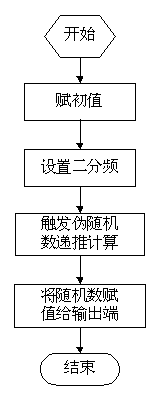
[0016] like figure 1 As shown, the specific steps of the present invention to generate the excitation signal PRMS:

[0017] 1. Assign an initial value to the seed and set the hold time. Add a pseudo-random signal to trigger the switch, the pseudo-random signal triggers the rising edge of the switch, and then assigns the initial value of 0 to the seed and sets the holding time T=300ms.

[0018] 2. Set the frequency by two. Add two on-delay timers TON1 and TON2, and the timing time is T / 2 respectively; then set the relationship between timers TON1 and TON2: TON1 first turns on delay T / 2, then turns on TON2, and TON2 turns on Then disconnect TON1 to make TON1 re-time.

[0019] 3. Set the recursive calculation of random numbers to be triggered every hold time T. In order to ensure that the calculation process of pseudo-random numbers is triggered every T time since the signal is triggered, the falling edge of the on-delay timer TON2 is added; then according to the recursive fo...


PUM


Abstract

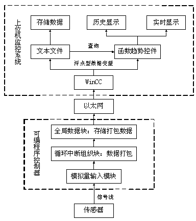
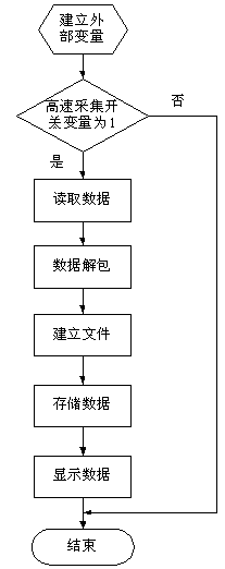
The invention discloses a system identification method based on an upper computer and a programmable logic controller. According to the system identification method, stimulus signal-pseudorandom multidigit signals PRMS used for identification are generated by programming on the programmable logic controller; the characteristics of the upper computer WinCC and the lower computer programmable logic controller are fully used for collecting input and output data at a high speed (the collection cycle can reach 5 ms), and in this way it is guaranteed that sufficient data can be used for system identification. In order to achieve high-speed data collection of the WinCC, the signal data continuously collected are sequentially stored in data blocks on the programmable logic controller, a plurality of external variables corresponding to all process variables in the data blocks are set up in the upper computer WinCC, and the high-speed data collection of the WinCC is indirectly achieved in the mode that the multiple variables read continuous values of the same signal data. The simple, reliable and low-cost method is provided for system identification on industrial site.

Description

technical field [0001] The invention relates to a system identification method based on a host computer and a programmable controller. Background technique [0002] The upper computer WinCC + lower computer programmable logic controller (PLC) is the main form of the industrial field monitoring system. PLC is mostly used to realize switch control, analog input and output and logic operation functions, but it is rarely used for system identification research. On the one hand, it is because the excitation signal used for system identification has high requirements and must have rich changes, which can continuously stimulate all modes of the identified process, and it is not easy to use the programmable controller to generate the excitation signal; When the system is identified, the input and output data should be collected at a high speed in order to obtain a large amount of rich data. However, the minimum refresh period of WinCC is only 250ms, and the minimum data archiving ...

Claims


Application Information

Patent Timeline
Patent Type & Authority Applications(China)
IPC IPC(8): G05B19/418
CPCY02P90/02
Inventor 谭建平许洪韬杨俊许文斌周宇峰
Owner CENT SOUTH UNIV
Learn More