Startup boiler control system

A control system, a technology for starting boilers, applied in the directions of comprehensive factory control, comprehensive factory control, electrical program control, etc., can solve the problems of limited number of I/O channels, increased operation capacity, inconvenient maintenance, etc., to improve the degree of centralized control operation , the effect of improving the degree of automation and reducing labor costs

Active Publication Date: 2014-09-17
浙江大唐国际绍兴江滨热电有限责任公司
View PDF6 Cites 10 Cited by
  • Summary
  • Abstract
  • Description
  • Claims
  • Application Information

AI Technical Summary

Problems solved by technology

[0009] Although the simple control of the PLC side by the DCS is realized, the communication between these two systems must be achieved by hard wiring. Due to the low version of the configured PLC and the limited number of I / O channels, only a few command feedbacks are connected through hard wiring. DCS, so it is very difficult to realize the sequential start and stop of the start-up furnace by the existing system, which reduces the automation level of the whole unit
The communication between the two control systems uses a lot of hard wiring, which wastes control resources and sacrifices a lot of manpower in construction and design, and at the same time brings inconvenience to future maintenance.
Both sets of control systems are installed on site. Because there are still technical problems in communication with the DCS control system, the control of the start-up furnace must be carried out on site, and it is forced to deploy on-duty personnel on site. The management system of the mechanism requires only 6 to 8 personnel for centralized control. If the centralized control cannot be performed due to the start-up of the furnace control system and the on-duty personnel are assigned locally, the operation quota will increase accordingly, which seriously violates Datang International’s long-term safety production plan. The concept of insisting on centralized control and operation in the management system of effective mechanism

Method used


Image

  • Startup boiler control system
  • Startup boiler control system
  • Startup boiler control system

Examples


Embodiment Construction

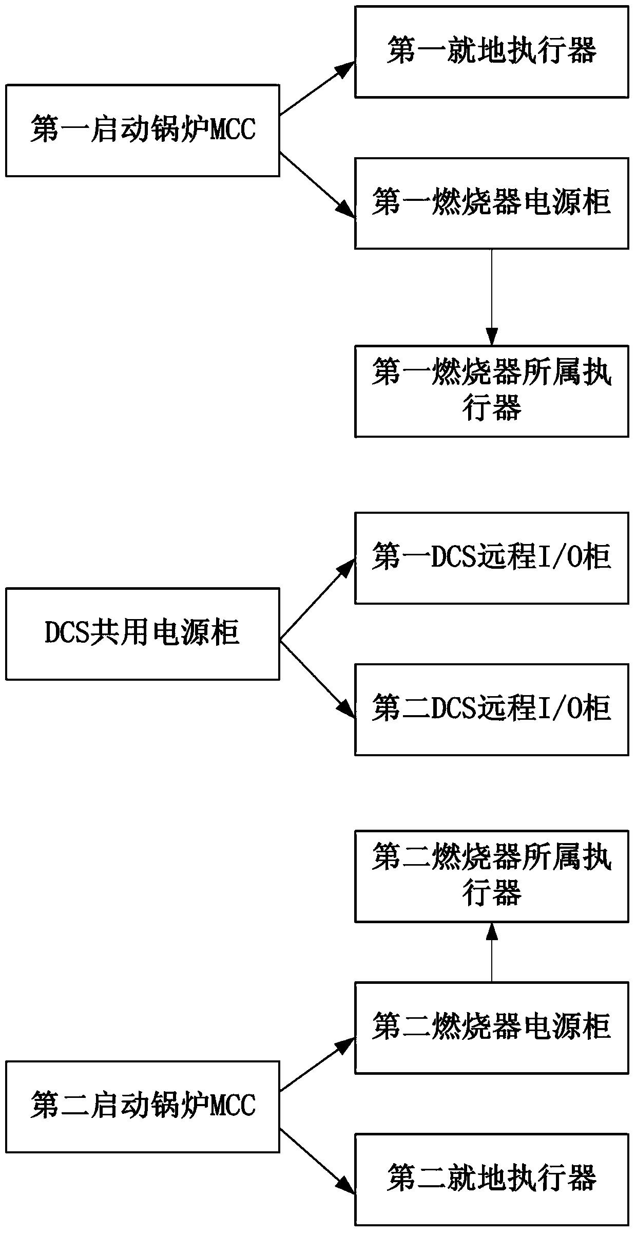
[0040] Such as figure 2 As shown, the start-up boiler control system of the present invention includes a power supply system, and the power supply system includes the first start-up boiler MCC, the second start-up boiler MCC and the DCS public power supply cabinet, and the local actuators and first burners belonging to the first start-up boiler Power supply cabinet, actuator of the first burner, remote I / O cabinet of the first DCS, local actuator of the second start-up boiler, power cabinet of the second burner, actuator of the second burner and remote I / O cabinet of the second DCS / O cabinet; the first start-up boiler MCC respectively supplies power to the local actuator belonging to the first start-up boiler and the first burner power supply cabinet; the second start-up boiler MCC respectively supplies power to the local actuator and the second burner belonging to the second start-up boiler The power supply cabinet supplies power; the DCS public power supply cabinet supplie...


PUM


Abstract

The invention relates to a startup boiler control system. The startup boiler control system comprises a power supply system. The power supply system comprises a first startup boiler MCC, a second startup boiler MCC and a DCS common power supply cabinet. The first startup boiler MCC supplies power to an on-site actuator which a first startup boiler belongs to and a first combustor power supply cabinet respectively. The second startup boiler MCC supplies power to an on-site actuator which a second startup boiler belongs to and a second combustor power supply cabinet respectively. The DCS common power supply cabinet supplies power to a first DCS remote I/O cabinet and a second DCS remote I/O cabinet respectively. The first combustor power supply cabinet supplies power to an actuator which a first combustor belongs to. The second combustor power supply cabinet supplies power to an actuator which a second combustor belongs to. Through the startup boiler control system, a circuit can be simplified, and reliability can be improved.

Description

technical field [0001] The invention relates to the field of power generation equipment, in particular to a control system for starting a furnace. Background technique [0002] DCS is the first system launched by HONEYWELL in 1975 after the advent of PLC in 1969. That is: TDC2000, it only has analog control. Subsequently, dozens of American instrument companies also launched their own systems. At the same time, due to the high profits of DCS, companies responsible for manufacturing transmission equipment and computer companies also began to be involved in the development and production of DCS. [0003] DCSs developed from different directions have some differences in structure and software. The software part of the DCS controller developed by the instrument company is more in line with the application habits of instrument engineers, especially the configuration method is more convenient. The PLC part designed by the transmission company is better. The man-machine interf...

Claims


Application Information

Patent Timeline
Patent Type & Authority Applications(China)
IPC IPC(8): G05B19/418
CPCY02P90/02
Inventor 边登鹏王凤明谢辉徐钰剑董坤张天宇周雪峰
Owner 浙江大唐国际绍兴江滨热电有限责任公司
Why Eureka
Try Eureka