Pixel drive circuit, display device and pixel drive method

A technology of pixel drive circuit and drive tube, which is applied in static indicators, instruments, etc., can solve problems affecting image display effects, uneven threshold voltage, uneven display brightness, etc., achieve uniform display brightness, solve threshold voltage drift, and improve Show the effect of the effect

Active Publication Date: 2014-09-17
BOE TECH GRP CO LTD +1
View PDF5 Cites 5 Cited by
  • Summary
  • Abstract
  • Description
  • Claims
  • Application Information

AI Technical Summary

Problems solved by technology

[0004] Due to reasons such as process technology and device aging, the threshold voltage (V th ) will drift, which causes the current flowing through each OLED pixel to vary depending on V th In addition, due to the non-uniformity of the threshold voltage of the driving TFT of each pixel, it will directly cause the current flowing through each pixel OLED to change, making the display brightness uneven, thus affecting the display effect of the entire image

Method used


Image

  • Pixel drive circuit, display device and pixel drive method
  • Pixel drive circuit, display device and pixel drive method
  • Pixel drive circuit, display device and pixel drive method

Examples


Embodiment 1

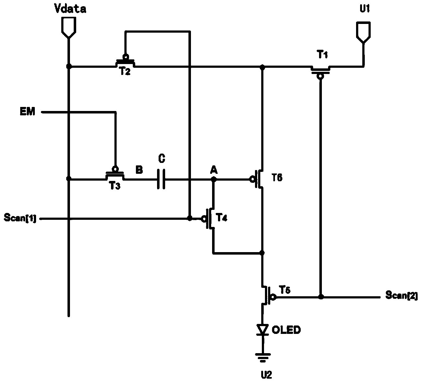
[0042]This embodiment provides a pixel driving circuit, which is used to drive the light-emitting element to make the light-emitting element emit light; it includes a signal line, a control line, a power supply unit and a driving unit, and also includes a compensation unit, a signal line, a control line, a power supply unit and The drive unit is respectively connected to the compensation unit; the power supply unit and the drive unit are used to provide power and drive the light-emitting element respectively; the signal line and the control line are respectively used to provide data signals and control signals for the compensation unit; the compensation unit is used to and the control signal to perform threshold voltage compensation on the driving unit.

[0043] like figure 2 As shown, the control line includes the first scan line EM, the second scan line Scan (1) and the third scan line Scan (2); the power supply unit includes the first power supply terminal U1 and the secon...

Embodiment 2

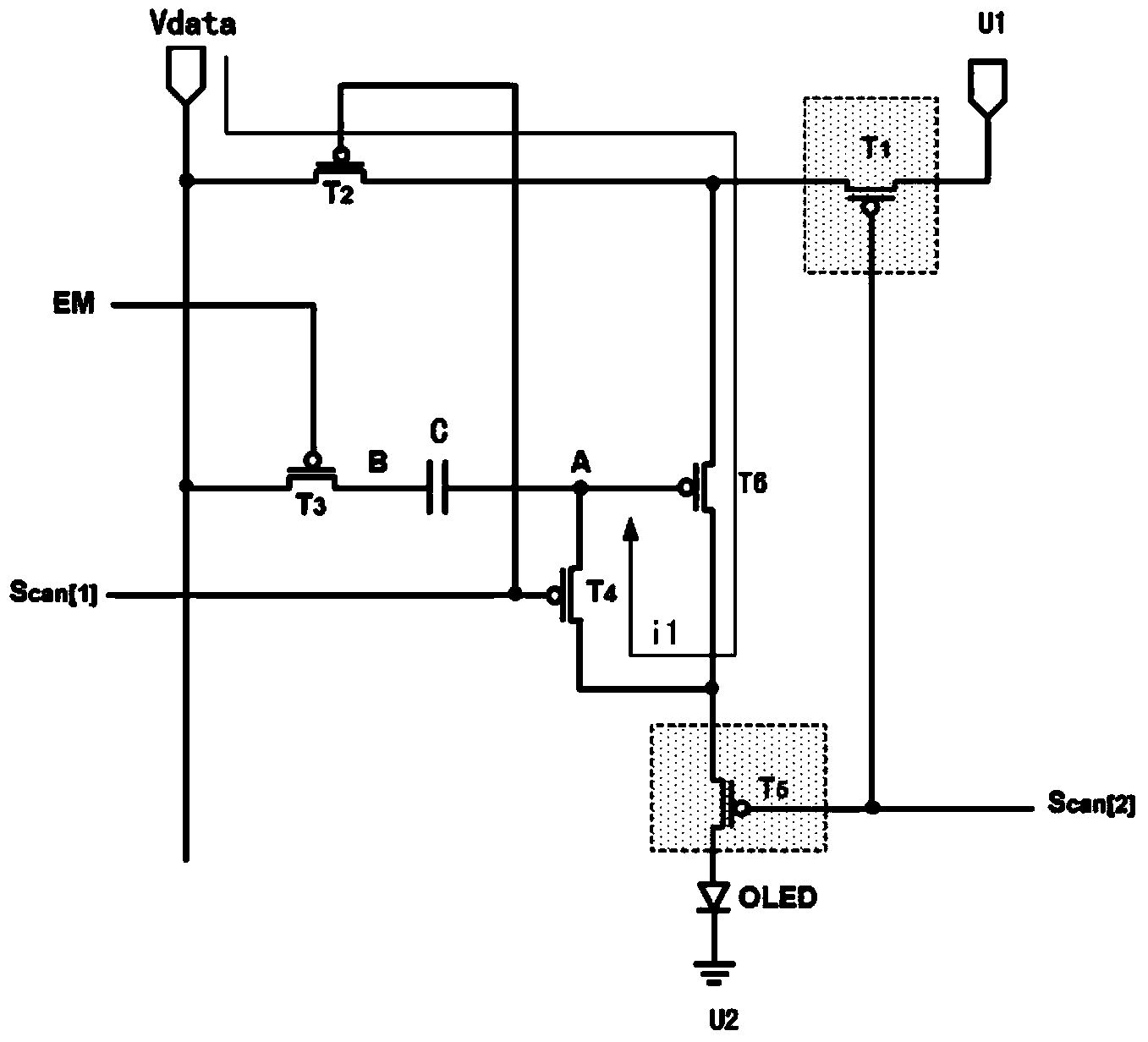
[0067] This embodiment provides a pixel driving circuit. The difference from Embodiment 1 is that in the driving phase of the pixel driving circuit, the first scan line remains on, the second scan line is off, the third scan line is on, and the first The switching tube, the third switching tube and the fifth switching tube are turned on, the second switching tube and the fourth switching tube are turned off, and the same data signal as that in the charging phase is applied to the signal line in the driving phase.

[0068] That is, in this driving phase, the potential of the first pole of the capacitor is still V p , correspondingly, the potential of the gate of the drive tube is V p -V th , according to the current formula when the drive tube reaches saturation, it can be obtained:

[0069] I OLED =K(V GS –V th ) 2

[0070] =K[V dd –(Vp –V th )–V th ] 2

[0071] =K(V dd –V p ) 2

[0072] As can be seen from the above current formula, in this embodiment, in the ...

Embodiment 3

[0076] This embodiment provides a display device, which includes a light-emitting element, and further includes the pixel driving circuit in any one of Embodiments 1-2, where the pixel driving circuit is connected to the light-emitting element for driving the light-emitting element.

[0077] By adopting the pixel driving circuit in any one of the embodiments 1-2, the display brightness of the display device can be made more uniform, thereby improving the display effect of the display device.


PUM


Abstract

The invention provides a pixel drive circuit, a display device and a pixel drive method. The pixel drive circuit comprises a signal line, a control line, a power unit and a drive unit, and further comprises a compensation unit, wherein the signal line, the control line, the power unit and the drive unit are connected with the compensation unit. The power unit is used for supplying power to a light-emitting element. The drive unit is used for driving the light-emitting element. The signal line is used for providing a data signal for the compensation unit. The control line is used for providing a control signal for the compensation unit. The compensation unit is used for conducting threshold voltage compensation on the drive unit according to the data signal and the control signal. The pixel drive circuit prevents working current of the drive unit from being influenced by the threshold voltage of the drive unit due to the arrangement of the compensation unit, and therefore the influences of the threshold voltage of the drive circuit on the working current of the drive unit are eliminated, the problem of threshold voltage drifting which is caused by the process manufacture procedure and long-time operation to the drive unit is thoroughly solved, and it is ensured that the display luminance of the light-emitting element is uniform.

Description

technical field [0001] The present invention relates to the field of display technology, in particular to a pixel driving circuit, a display device and a pixel driving method. Background technique [0002] Organic light-emitting display (AMOLED) is one of the hotspots in the field of flat panel display research today. Compared with liquid crystal display (LCD), OLED has the advantages of low energy consumption, low production cost, self-illumination, wide viewing angle and fast response speed. Currently, in OLEDs have begun to replace traditional LCD displays in display fields such as mobile phones, PDAs, and digital cameras. Among them, pixel driving is the core technical content of AMOLED display, which has important research significance. [0003] Unlike TFT-LCD, which uses a stable voltage to control brightness, OLED is current-driven and requires a stable current to control light emission. like figure 1 As shown, the traditional AMOLED pixel driving circuit adopts 2T...

Claims


Application Information

Patent Timeline
Patent Type & Authority Applications(China)
IPC IPC(8): G09G3/32G09G3/3225
CPCG09G3/32
Inventor 杨盛际孙泽斌王春雷刘英明李伟
Owner BOE TECH GRP CO LTD
Why Eureka
Try Eureka