

Modularized control rod driving system and method for horizontal reactor core structure
A technology of modular control and core structure, applied in the field of nuclear energy research, can solve the problem that the control rod assembly cannot be directly inserted into the core by its own weight, and achieve the effect of easy replacement and movement, compact structure and convenient maintenance
- Summary
- Abstract
- Description
- Claims
- Application Information
AI Technical Summary
Problems solved by technology
Method used
Image

Examples
Embodiment 1
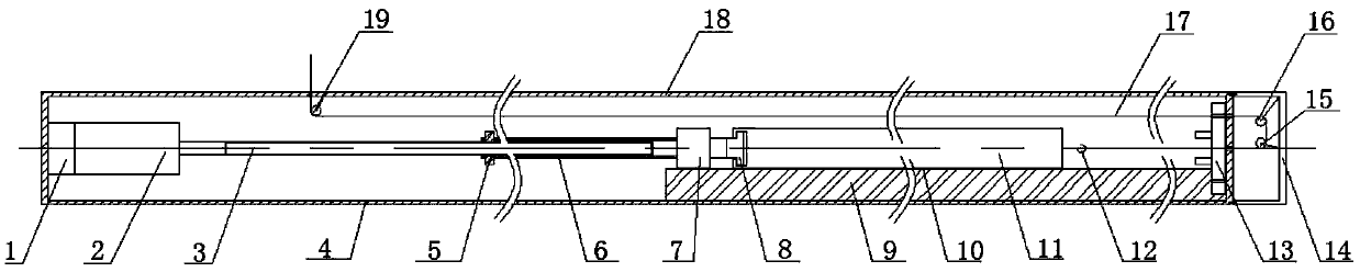
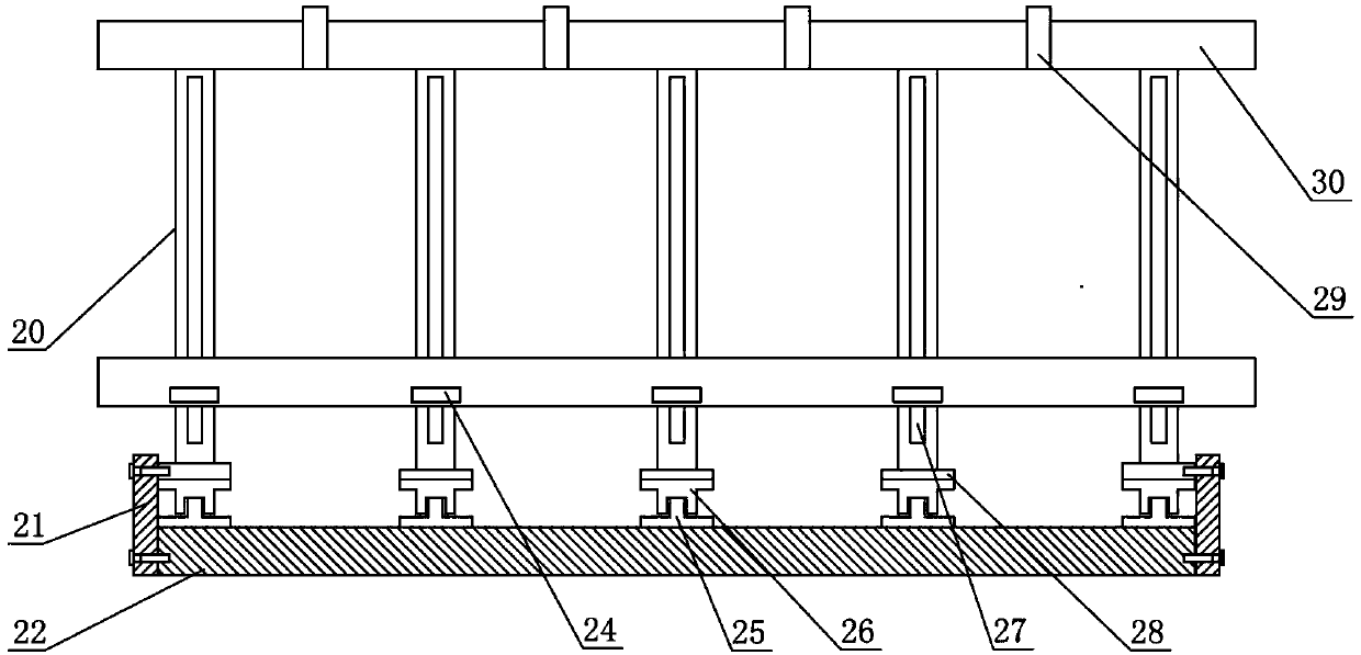
[0058] Such as Figure 1 ~ Figure 3 As shown, the modular control rod drive system for horizontal core structure includes the following components: encoder 1; drive motor 2; ball screw 3; nut 5; nut sleeve 6; electromagnetic clutch 7; control rod assembly 11; traction steel wire 17; fixed support 20; traction counterweight 35.
[0059] The working principle of this embodiment is as follows:
[0060] Moving steps: the control rod assembly 11 connected with the gripper is connected with the nut sleeve 6 through the electromagnetic clutch 7, and the nut sleeve 6 is connected with the ball screw through the nut 5, and the ball screw is driven by the driving motor to drive the nut sleeve to reciprocate Movement, so that the control rod assembly moves to a predetermined position, and the rod position is determined by encoder 1;
[0061] Rapid rod drop step: the electromagnetic clutch 7 is powered off, the control rod assembly 11 is separated from the nut casing 6, the traction cou...
Embodiment 2
[0066] As shown in the figure, this embodiment discloses a modular control rod driving device with the following structure in order to improve the degree of system integration and improve the usability and reliability of the driving device.
[0067] The described modularized control rod driving device comprises an encoder 1, the encoder 1 is fixed on the tail end of the driving motor 2, the driving motor is fixed on the bottom of the housing 4, the ball screw 3 is fixed on the rotating shaft of the driving motor 2, and the ball screw 3 passes through the The nut 5 is threaded to complete the connection, the nut 5 is fixed on the nut sleeve 6, the nut sleeve 6 and the electromagnetic clutch 7 are fixed by screws, and the electromagnetic clutch 7 is connected to the control rod assembly gripper 8 of the control rod assembly 11 by magnetic force, and the control rod The tail hook 12 of the control rod assembly is installed at the tail of the assembly 11, and the traction steel wir...
Embodiment 3
[0070] Such as Figure 1 ~ Figure 3 As mentioned above, this embodiment provides a passive shutdown system suitable for a research reactor with a horizontal core structure on the basis of the above embodiments.
[0071] The working principle of the passive shutdown system described in this embodiment is as follows:
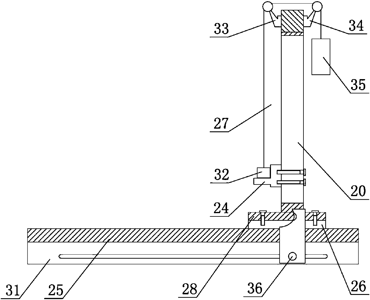
[0072] The traction counterweight 35 is suspended on the fixed support 20, and the distance between it and the ground is greater than the maximum stroke of the control rod assembly 11, so as to ensure that the control rod assembly 11 can be completely inserted into the core under its traction.
[0073] The traction counterweight 35 is connected to the control rod assembly 11 through the traction steel wire 17 and the diverting pulley block composed of 5 pulleys. Under normal working conditions, the traction counterweight 35 has gravitational potential energy. When emergency shutdown occurs, the electromagnetic clutch 7 disconnects the nut sleeve The connection be...
PUM
 Abstract
Description
Claims
Application Information