Laminate type magnetic ball

A chip and magnetic bead technology, applied in the direction of electrical components, inductors, circuits, etc., can solve the problems of low rated current, limited application range, high DC resistance, etc.

Inactive Publication Date: 2014-09-17
SHENZHEN ZHENHUA FU ELECTRONICS
View PDF5 Cites 3 Cited by
  • Summary
  • Abstract
  • Description
  • Claims
  • Application Information

AI Technical Summary

Problems solved by technology

[0003] However, the traditional laminated chip beads have low rated cu

Method used


Image

  • Laminate type magnetic ball
  • Laminate type magnetic ball
  • Laminate type magnetic ball

Examples


Embodiment Construction

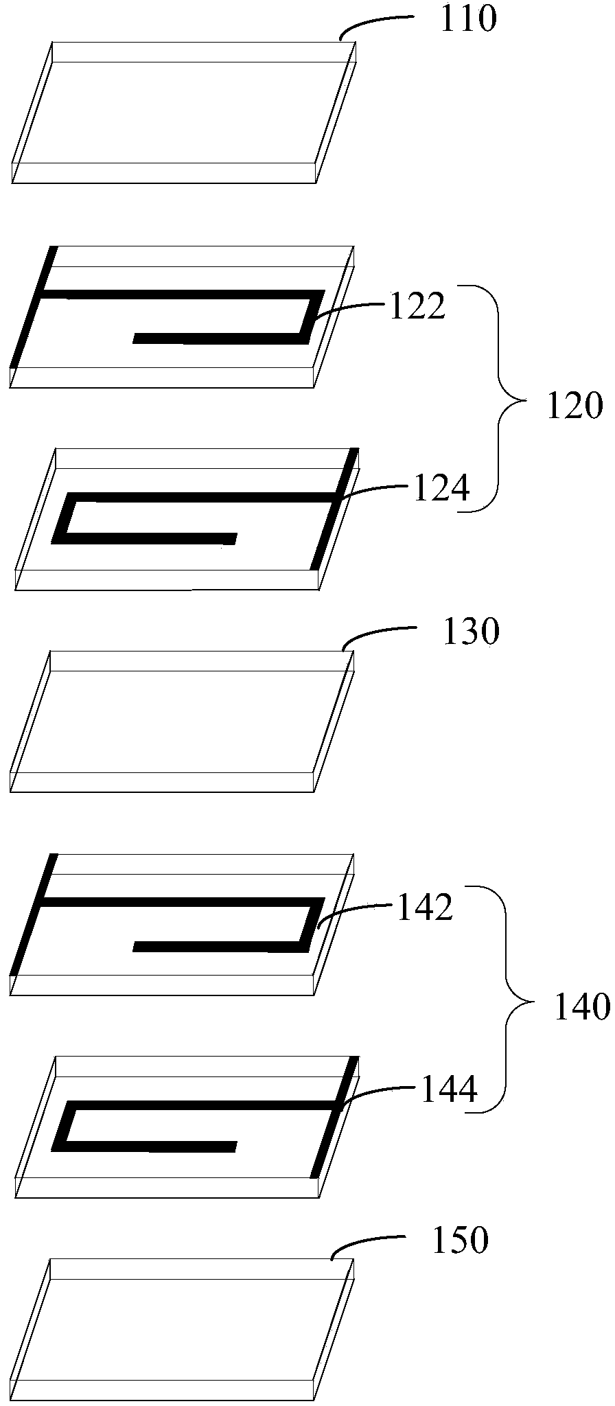
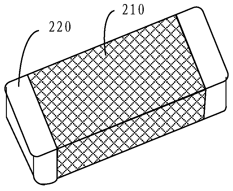
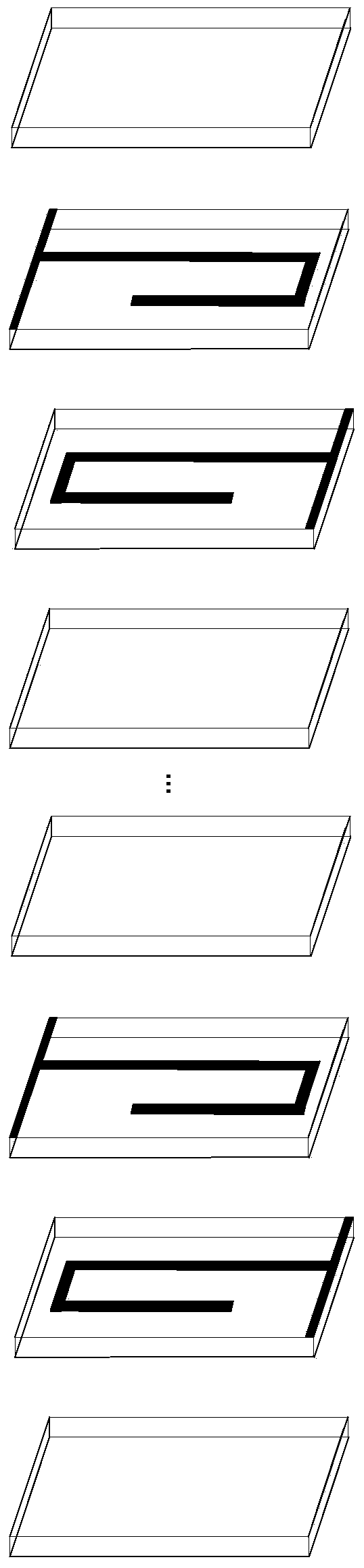
[0016] Please refer to figure 1 with figure 2 , are respectively an internal structure diagram and an external structure diagram of a laminated chip magnetic bead according to an embodiment. figure 1 As shown, the laminated chip magnetic bead includes a base membrane 110 , an inner electrode coil 120 , a base membrane 130 , an inner electrode coil 140 and a base membrane 150 .

[0017] In this embodiment, the base membrane 110 , the base membrane 130 and the base membrane 150 are all ferrite material membranes, which are formed by tape casting during fabrication.

[0018] A complete inner electrode coil 120 includes an inner electrode 122 and an inner electrode 124, and the inner electrode 122 and the inner electrode 124 are connected to each other through a metal conductor. The inner electrode coil 120 is located between different layers of base membranes (base membrane 110 , base membrane 130 ). Similarly, the inner electrode coil 140 includes an inner electrode 142 and ...


PUM


Abstract

A laminate type magnetic ball comprises at least three layers of basal body diaphragms, end electrodes which are located on two sides of the basal body diaphragms and internal electrode coils which are arranged among different basal body diaphragms, wherein the internal electrode coils in different layers are same in structure, and wiring is realized in a parallel multipled mode. According to the laminate type magnetic ball, the rate current of the laminate type magnetic ball is greatly improved, and the direct current resistance is reduced at the same time.

Description

technical field [0001] The invention relates to the field of electronic components, in particular to a laminated chip magnetic bead. Background technique [0002] With the development of industrial automation, especially the development of modern communication industry (such as mobile phone and other portable terminal products), laminated chip magnetic beads have become a key product in the field of electronic components due to their advantages of good magnetic shielding and miniaturization. Its applications range from mobile devices, computers, servers, personal navigation systems, personal multimedia devices, and automotive systems. [0003] However, the traditional laminated chip beads have low rated current and high DC resistance, which limits their application range. Contents of the invention [0004] Based on this, it is necessary to provide a laminated chip magnetic bead with high rated current and low DC resistance. [0005] A laminated chip magnetic bead, compri...

Claims


Application Information

Patent Timeline
IPC IPC(8): H01F17/00H01F37/00
Inventor 王智会张小霞肖倩曹华春刘奕林尹红葵邵琴
Owner SHENZHEN ZHENHUA FU ELECTRONICS
Why Eureka
Try Eureka