Inductor assembly and manufacturing method therefor

A manufacturing method and inductor technology, applied in the field of inductors, can solve problems such as electromagnetic interference and low space utilization of inductors, and achieve the effects of reducing volume, improving magnetic shielding effect, and improving space utilization rate.

Active Publication Date: 2016-06-29
SHENZHEN ZHENHUA FU ELECTRONICS
View PDF9 Cites 2 Cited by
  • Summary
  • Abstract
  • Description
  • Claims
  • Application Information

AI Technical Summary

Problems solved by technology

[0003] The purpose of the present invention is to provide an inductor assembly, aiming to solve the problems of low space utilization and easy generation of electromagnetic interference in existing inductors

Method used


Image

  • Inductor assembly and manufacturing method therefor
  • Inductor assembly and manufacturing method therefor
  • Inductor assembly and manufacturing method therefor

Examples


no. 1 example

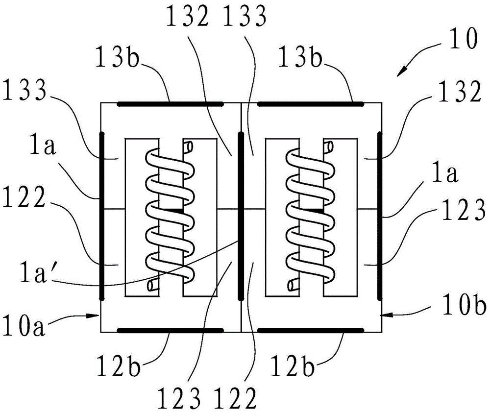
[0034] Please refer to figure 2 , image 3 . In this embodiment, the inductor assembly 2 includes two figure 2 The illustrated inductors are respectively marked as inductor 10a and inductor 10b for specific distinction. The central axes of the inductance coils 11 of the inductors 10a, 10b are parallel to each other. figure 1 , figure 2 The central axes of the inductance coils 11 of the middle inductors 10a and 10b both extend in the vertical direction. The side cylinders of the two inductors 10a and 10b are in contact, that is, the side column 132 of the inductor 10a is in contact with the side column 133 of the inductor 10b, and the side column 123 of the inductor 10a is in contact with the side column 122 of the inductor 10b. offset, and then closely arranged into a 1×2 rectangular array. At the position where the outer sides of the magnetic cores 12 of the two adjacent inductors 10a, 10b meet, the air gap 1a of the inductor 10a and the air gap 1a of the inductor 10...

no. 2 example

[0040] Please refer to image 3 and Figure 4 . Compared with the inductor assembly of the first embodiment, the inductor assembly in this embodiment further includes a fixing plate 14 and four conductive inserts 16a, 16b, 16c and 16d vertically fixed on the fixing plate 14 . Wherein, the fixing plate 14 is packaged together with the inductor 10 , that is, the fixing plate 14 and the inductor 10 are fixed by the filling material 15 . The filling material 15 can be selected from resin material, such as polypropylene material, and the material of the fixing plate 14 can be selected from phenolic resin. Wherein, the conductive insert 16a is electrically connected to one end of the inductance coil 11 of the inductor 10b, and the conductive insert 6b is electrically connected to the other end of the inductance coil 11 of the inductor 10b; the conductive insert 16c is electrically connected to one end of the inductance coil 11 of the inductor 10a , the conductive insert 16d is el...

no. 3 example

[0043] Please refer to figure 2 , image 3 , Figure 5 . In this embodiment, the difference from the first embodiment is that the inductor assembly 10 in this embodiment further includes two figure 2 The shown inductors are respectively marked as inductors 10c and 10d for ease of distinction.

[0044] Among these four inductors, the relative positional relationship of the inductors 10c and 10d is exactly the same as that of the inductors 10a and 10b in the second embodiment. In this embodiment, the bottom post 124 of the inductor 10a is in contact with the bottom post 134 of the inductor 10c, and the air gap 12b of the inductor 10a is opposite to the air gap 13b of the inductor 10c. The extension direction of the air gap 13b together forms a new air gap 1b. Similarly, the relative positional relationship of the inductors 10b, 10d is exactly the same as that of the inductors 10a, 10c, that is, the bottom column 124 of the inductor 10c is in contact with the bottom column...


PUM


Abstract

The invention provides an inductor assembly. The inductor assembly is formed by multiple inductors in a packaging manner, wherein each inductor comprises an inductance coil and two E-shaped magnetic cores; each magnetic core comprises a bottom column, and a middle column and two side columns protruding from the bottom column to the same side; the bottom column, the middle column and the side columns jointly form a magnetic core plane; the two side columns are positioned on the two sides of the middle column respectively; the opening ends of the two magnetic cores face each other; the middle columns of the two magnetic cores face each other; the side columns of the two magnetic cores prop against each other; two magnetic cores form two magnetic loops; the inductance coils are wound around the middle columns of the corresponding two magnetic cores; an air gap is formed between the middle columns of the two magnetic cores; the inductors are tightly arranged on the magnetic core planes in a rectangular array manner; and the magnetic cores of every two adjacent inductors prop against each other. The invention also provides a manufacturing method for the inductor assembly. The external electromagnetic interference of the inductor assembly is greatly lowered; the space utilization rate is obviously improved; and the inductor assembly has a good magnetic shielding effect even if the inductor assembly is small in volume.

Description

technical field [0001] The present invention relates to the technical field of inductors, and more particularly relates to an inductor component and a manufacturing method thereof. Background technique [0002] Electronic and electrical products are rapidly developing towards miniaturization and multi-functionalization. In these products, power inductors are relatively large in size, especially when multiple power inductors are required, and their space utilization rate is lower. Many It hinders the miniaturization of the product to a certain extent; moreover, the magnetic shielding effect of these power inductors is poor, and it is easy to generate electromagnetic interference to other circuits, especially when the product integrates various functional modules, it will cause various problems to the multifunctional design and realization of the product. an inescapable limitation. Therefore, the existing inductors need to be further improved. Contents of the invention [...

Claims


Application Information

Patent Timeline
Patent Type & Authority Applications(China)
IPC IPC(8): H01F17/04H01F27/24H01F27/30H01F41/02H01F41/04
Inventor 胡利华王海樊应县陈益芳王智会黄丹艳
Owner SHENZHEN ZHENHUA FU ELECTRONICS
Why Eureka
Try Eureka