Disk high-voltage direct-current generator
A high-voltage DC and generator technology, applied in the magnetic circuit static parts, magnetic circuit shape/style/structure, magnetic circuit rotating parts and other directions, can solve the problems of DC voltage fluctuation, iron loss, etc., to achieve a small moment of inertia, The effect of low internal resistance and a wide range of material sources
- Summary
- Abstract
- Description
- Claims
- Application Information
AI Technical Summary
Problems solved by technology
Method used
Image
Examples
Embodiment approach 1
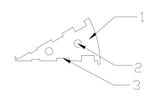
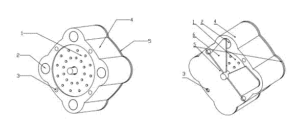
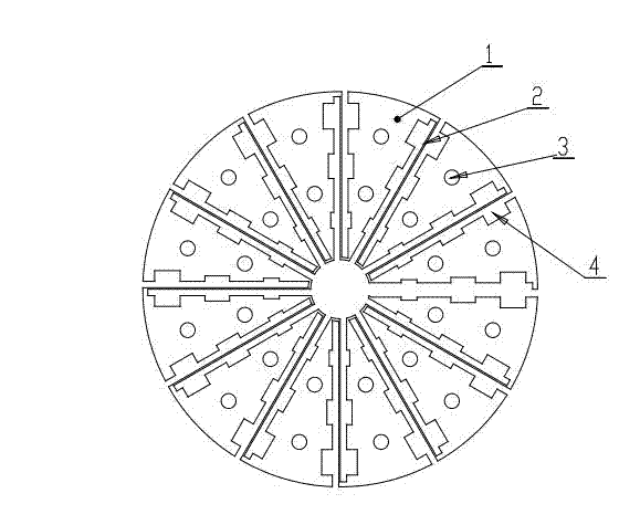
[0023] make figure 1 For the power generation unit shown, place the positioning holes of the power generation unit on a special fixture for positioning, arrange them evenly and weld them figure 2 The 2 connecting wires shown in , require the welded joint resistance to be small and firm. After sequentially welding the 12 power generation units in this example, they are assembled into figure 2 As shown in the single-chip power generation disc, there is a connecting wire in the single-chip disc, which needs to weld the inner protrusion of the last unit of the power generation disc on this layer with the outer end protrusion of a power generation unit on the previous layer, and then weld them sequentially. The remaining power generation units on the next layer are welded until all the power generation units are completed, so that the basic skeleton of the generator rotor is made, and then the Figure 5 Install on the middle input shaft end cover Figure 4 Insulation board, pr...
Embodiment approach 2
[0040] The production of the generator rotor is as in Scheme 1. The generator uses multiple rotors to rotate at the same time, and the rotation speed of the rotors is kept the same through mechanical transmission, and the steering can be the same or reversed.
[0041] The magnetic field source on the stator of the generator can be excited by permanent magnets or electromagnetic coils. Now, the scheme of using two rotors for power generation will be described.
[0042] The two rotors are installed side by side in the same stator, and the rotors are connected by gears or pulleys, and the two have the same rotational angular velocity of the rotors. The excitation magnetic field adopts a horseshoe-shaped magnet frame directly above the two generator rotors, so that the magnetic field generated by the magnets forms a magnetic circuit with the magnet or yoke at the other end of the rotor through the paramagnetic material on the two rotors, so that as long as the input shaft is driven...
Embodiment approach 3
[0046] The generator of this structure can also be used as a DC motor. If the permanent magnet is used as the magnetic pole, it can run continuously only by connecting the DC power supply. If the electromagnet is used for excitation, it is similar to the existing motor to easily realize the conversion of the generator and the motor. . Due to the characteristics of this device, the internal resistance is low, the iron loss and copper loss are low, and the volume of the generator is small. When used as a DC motor, it can achieve high torque output with a small DC voltage.
[0047] At this time, the magnetic field of the motor repeatedly passes through the stacked discs. After the cables at both ends of the discs are energized, the current passes through each power generation unit in turn, and each unit is subjected to the action of electromagnetic force, so that the discs generate torque around the rotating shaft. When the number of disc layers in the motor is large, even if th...
PUM
| Property | Measurement | Unit |
|---|---|---|
| Thickness | aaaaa | aaaaa |
| Diameter | aaaaa | aaaaa |
Abstract
Description
Claims
Application Information
 - R&D
- Intellectual Property
- Life Sciences
- Materials
- Tech Scout
- Unparalleled Data Quality
- Higher Quality Content
- 60% Fewer Hallucinations
Browse by: Latest US Patents, China's latest patents, Technical Efficacy Thesaurus, Application Domain, Technology Topic, Popular Technical Reports.
© 2025 PatSnap. All rights reserved.Legal|Privacy policy|Modern Slavery Act Transparency Statement|Sitemap|About US| Contact US: help@patsnap.com


