
Precise electric cylinder

An electric cylinder, precise technology, applied in the direction of electric components, electrical components, electromechanical devices, etc., can solve problems such as unstable friction, difficult precise control, and restrictions on electric cylinders, so as to eliminate sliding wear, reduce system noise, and prolong The effect of service life

Inactive Publication Date: 2014-09-17
SHANGHAI AORUI CONTROL SYST
View PDF10 Cites 16 Cited by
  • Summary
  • Abstract
  • Description
  • Claims
  • Application Information

AI Technical Summary

Problems solved by technology

Although this prior art adopts rolling bearings as the guiding structure of the actuating push rod, instead of the guiding mode of the feather key and the keyway, the sliding is replaced by rolling in this link, but the shaft sleeve is used to support the push rod at the output end of the push rod. In the linear telescopic reciprocating motion of the push rod, this link is still sliding friction, especially when the actuator is actually used, the push rod often bears a certain radial force. At this time, under the action of the radial force, the gap between the bushing and the push rod The friction between them will rise sharply, and the wear will increase. At the same time, the unstable friction force inside the actuator will make it extremely difficult to precisely control the position, speed and force of the end of the push rod.
In summary, due to the various disadvantages caused by the sliding friction of the existing electric cylinder guide parts or the support parts at the output end of the piston rod, the application of electric cylinders in many occasions with high control precision and high durability requirements is limited.

Method used


Image

  • Precise electric cylinder
  • Precise electric cylinder
  • Precise electric cylinder

Examples


Embodiment 1

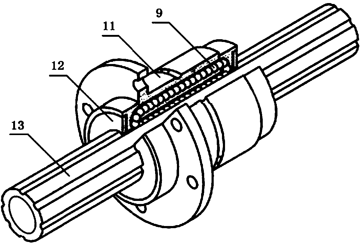
[0027] like figure 1 As shown, this embodiment includes: a cylinder 6, a screw pair composed of a screw shaft 1 and a screw nut 7, a thrust bearing 5 and a bearing seat 4, and a cylindrical piston rod 13, wherein: the screw shaft 1 is along the cylinder The central axis of the cylinder 6 is arranged, the screw shaft 1 passes through the thrust bearing 5, and is fixed with the inner ring of the thrust bearing through the shaft shoulder and the lock nut 2, and the outer ring of the thrust bearing 5 is matched with the inner hole of the bearing housing 4, The bearing plate 3 is fixed to the bearing seat 4, so that the screw shaft 1 is axially positioned, and the thrust bearing 5 is composed of a pair of thrust bearings, which can be a pair of angular contact thrust bearings or a pair of tapered rollers Bearing, cylinder 6 and bearing seat 4 are fixedly connected, the connection method can be through bolts or turning thread at the matching part of cylinder 6 and bearing seat 4, sc...


PUM


Abstract

A precise electric cylinder comprises a driving motor, a cylinder barrel, a lead screw pair, a thrust bearing, a hollow barrel-shaped piston rod and a ball spline sleeve, wherein the lead screw pair is composed of a lead screw shaft and a lead screw nut. The lead screw shaft is arranged along the central axis of the cylinder barrel, the power input end of the lead screw shaft is in transmission connection with an output shaft of the driving motor, the lead screw shaft is axially positioned through the thrust bearing, an outer ring of the thrust bearing and the cylinder barrel are fixed coaxially, the lead screw nut and the barrel-shaped piston rod are coaxially and fixedly connected, and the other end, opposite to the power input end, of the lead screw shaft stretches into the hollow barrel-shaped piston rod. When the driving motor drives the lead screw shaft to rotate and the piston rod is driven to conduct reciprocating motion, rolling of balls replaces original sliding friction between the piston rod and a supporting component and between the piston rod and a guiding component, so that abrasion is reduce, and efficiency, control accuracy and reliability are improved.

Description

technical field [0001] The invention relates to an electric linear actuator for converting rotary motion into linear motion, in particular to a precision electric cylinder in which a piston rod is simultaneously supported and guided by rolling. Background technique [0002] Electric cylinder is an electric linear actuator that has become more and more widely used in recent years. It has many advantages such as energy saving, low noise, no pollution, high efficiency, and simple application layout. It has gradually replaced traditional hydraulic and pneumatic linear actuators in many application fields. actuator. The principle of the electric cylinder is that the drive motor drives the screw shaft to rotate through direct connection, or the transmission belt and the pulley, or the gear pair, and the screw nut is fixedly connected with the hollow cylindrical piston rod to convert the rotation of the screw shaft into a screw Linear movement of nut and piston rod. In order to r...

Claims


Application Information

Patent Timeline
IPC IPC(8): H02K7/06
Inventor 李旻
Owner SHANGHAI AORUI CONTROL SYST
Learn More