Three-dimensional image correction device and three-dimensional image correction method

A technology of 3D image and correction device, applied in image communication, TV, electrical components, etc., can solve problems such as wrong depth map, inconvenience, and affecting the quality of 3D display

Inactive Publication Date: 2016-08-10
AU OPTRONICS CORP
View PDF4 Cites 0 Cited by
  • Summary
  • Abstract
  • Description
  • Claims
  • Application Information

AI Technical Summary

Problems solved by technology

[0004] However, when the above-mentioned depth generator processes the input source, there will be some situations. For example, each part of the same object basically has the same depth information, but the depth generator sometimes divides the same object in the vertical direction. Interpret two different depth information, resulting in wrong depth map
Once the depth image plotter generates 3D images based on the wrong depth map, the above-mentioned objects will produce 3D jagged phenomenon, seriously affecting the quality of 3D display
[0005] This shows that above-mentioned existing mode obviously still has inconvenience and defective, and needs to be improved
In order to solve the above problems, related fields have tried their best to find a solution, but a suitable solution has not been developed for a long time.

Method used

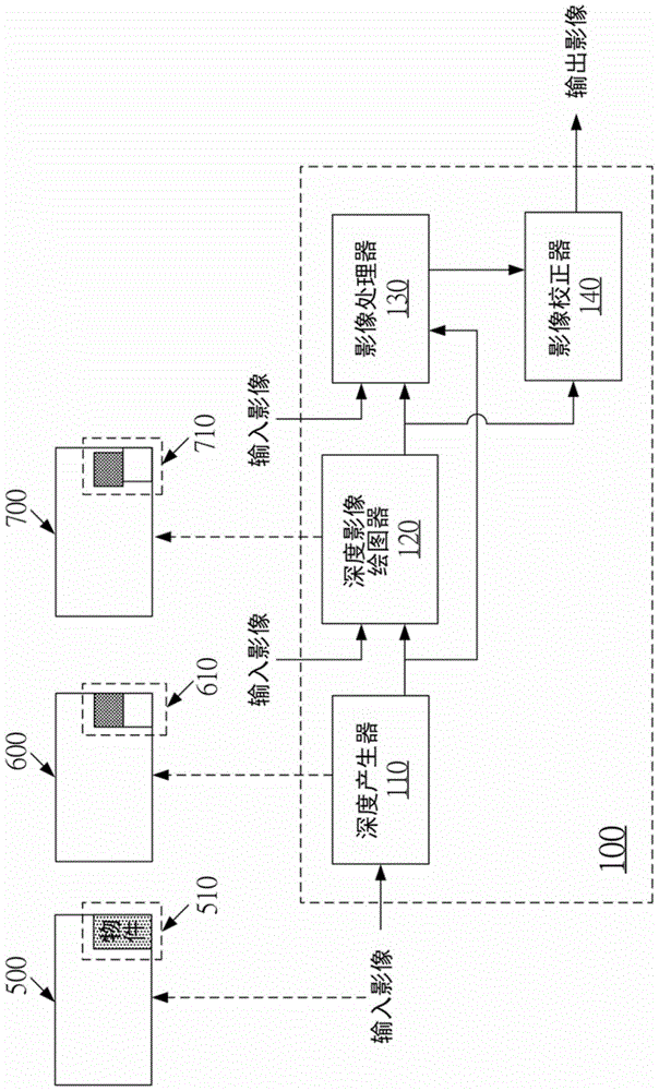
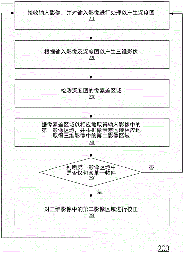
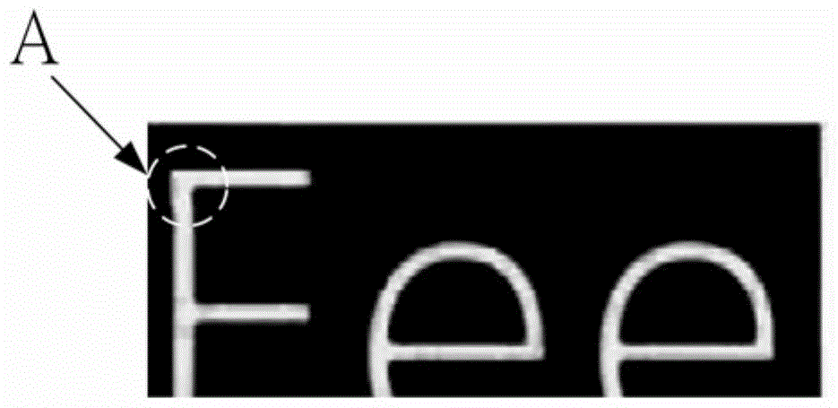

Image

  • Three-dimensional image correction device and three-dimensional image correction method
  • Three-dimensional image correction device and three-dimensional image correction method
  • Three-dimensional image correction device and three-dimensional image correction method

Examples


Embodiment Construction

[0042] In order to make the description of the content of the present invention more detailed and complete, the following provides an illustrative description of the implementation aspects and specific embodiments of the present invention; but this is not the only form for implementing or using the specific embodiments of the present invention. The description covers features of various embodiments as well as method steps and their sequences for constructing and operating those embodiments. However, other embodiments can also be used to achieve the same or equivalent functions and step sequences.

[0043] Unless otherwise defined in this specification, the meanings of scientific and technical terms used herein are the same as those commonly understood and commonly used by those skilled in the art to which this invention belongs. In addition, the singular nouns used in this specification include the plural forms of the nouns, and the plural nouns used also include the singular ...


PUM


Abstract

The invention relates to a three-dimensional image correction device, which includes a depth generator, a depth image plotter, an image processor and an image corrector. The depth generator is used for receiving an input image and processing the input image to generate a depth map. The depth image plotter is used to generate a 3D image according to the input image and the depth map. The image processor is used to detect pixel difference regions of the depth map. The image processor correspondingly detects the first image area in the input image according to the pixel difference area, and correspondingly detects the second image area in the 3D image according to the pixel difference area. The image processor is used for judging whether the first image area contains only a single object. The image corrector is used for correcting the second image area in the 3D image when the first image area only contains a single object.

Description

technical field [0001] The present invention relates to an image processing system and an image processing method, and in particular to a 3D image correction device and a 3D image correction method. Background technique [0002] With the advancement of technology, the video playback mode has gradually evolved from the traditional two-dimensional (Two Dimension, 2D) video playback mode to a three-dimensional (Three Dimension, 3D) video playback mode. Especially after the release of the Avatar movie in 2009, it led a trend of 3D images, and manufacturers in the display industry launched 3D displays one after another to meet the needs of consumers. [0003] Since 3D technology has not yet been popularized, 3D signal sources are relatively scarce. To solve this problem, multiple images or a single image are currently used as an input source, and the 3D display uses its internal depth generator to process the above-mentioned input source to generate a depth map, and then the dep...

Claims


Application Information

Patent Timeline
Patent Type & Authority Patents(China)
IPC IPC(8): H04N13/00H04N15/00H04N17/00
Inventor 许宏齐苏峻贤蔡富全和家璞
Owner AU OPTRONICS CORP
Why Eureka
Try Eureka