Energy-efficient transmission device

A transmission, high-efficiency and energy-saving technology, applied in the field of high-efficiency and energy-saving transmission and transmission, can solve the problems of damage to the reducer, troublesome assembly, overload of the reducer, etc., to avoid overload damage, reduce contact strength, and easy to assemble.

Inactive Publication Date: 2014-09-24
JIANGSU TIANYU ENVIRONMENTAL PROTECTION GRP CO LTD
View PDF0 Cites 0 Cited by
  • Summary
  • Abstract
  • Description
  • Claims
  • Application Information

AI Technical Summary

Problems solved by technology

The structure of the existing center-driven mud scraper is relatively complicated, and the assembly is troublesome. Due to the long-term sedimentation of the sludge in the sewage trea

Method used


Image

  • Energy-efficient transmission device

Examples


Embodiment Construction

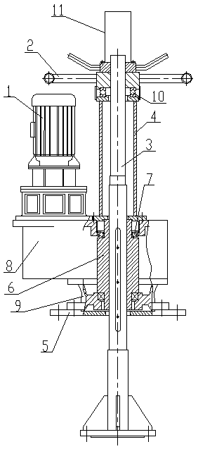
[0011] A high-efficiency energy-saving transmission device, including a reducer 1, a hand wheel 2, a transmission shaft 3, an adjustment bracket 4 and a base plate 5, the upper end of the output gear 6 in the reducer 1 is installed on the upper end of the reducer casing 8 through a bearing I7, and the output The lower end of the gear 6 passes through the reducer casing 8 and is installed in the through hole of the underframe 9 at the lower end of the reducer casing 8 through the bearing I7. The underframe 9 is installed on the bottom plate 5. Internally connected to the through hole of the output gear 6, the transmission shaft 3 can move up and down in the axial through hole of the output gear 6, the upper end of the transmission shaft 3 is covered with an adjustment bracket 4, and the hand wheel 2 is connected with the screw thread on the outer surface of the upper end of the transmission shaft 3 , There is a bearing II10 between the hand wheel 2 and the adjustment bracket 4; ...


PUM


Abstract

The invention relates to an energy-efficient transmission device, comprising a speed reducer, a hand wheel, a transmission shaft, an adjusting support and a base plate, wherein the upper end of an output gear in the speed reducer is installed on the upper end of a speed reducer box through a bearing I, the lower end of the output gear penetrates the speed reducer box and is installed in a through hole in an underframe located at the lower end of the speed reducer box through the bearing I, the underframe is mounted on the base plate, the axial center of the output gear is provided with a through hole, the transmission shaft is in internal connection with the through hole of the output gear and can move up and down in the axial through hole of the output gear, the upper end of the transmission shaft is sleeved by the adjusting support, the hand wheel is connected with thread at the outer surface of the upper end of the transmission shaft, and a bearing II is arranged between the hand wheel and the adjusting support. The energy-efficient transmission device has a simple structure and is easy to assemble; when the concentration of sludge in a sewage treating pool is too high or too great, the transmission shaft is lifted by rotating the hand wheel, so a scraping arm is lifted, contact strength of a scraper plate and sludge is reduced, and overload damage of the speed reducer is avoided.

Description

technical field [0001] The invention relates to a transmission device of a centrally driven mud scraper, in particular to a high-efficiency and energy-saving transmission device, which belongs to the technical field of sewage treatment equipment. Background technique [0002] The center-driven sludge scraper uses the reducer to drive the transmission shaft to rotate, so that the scraper arm rotates with the transmission shaft, and the scraper gradually scrapes the side of the sludge oil pool to the pool center pit, and then through the action of hydrostatic pressure Drain the sludge out of the pool. The structure of the existing center-driven mud scraper is relatively complicated, and the assembly is troublesome. Due to the long-term sedimentation of the sludge in the sewage treatment tank, the sludge concentration will be too high or too large, and the scraper cannot scrape the sludge, resulting in an overload of the reducer. , thus causing damage to the reducer. Content...

Claims


Application Information

Patent Timeline
IPC IPC(8): B01D21/18
Inventor 方跃飞潘庆权彭友贵
Owner JIANGSU TIANYU ENVIRONMENTAL PROTECTION GRP CO LTD
Why Eureka
Try Eureka