Hydraulic control loop for impacting cutting teeth and impacting cutting tooth assembly

A control loop, hydraulic technology, applied in cutting machinery, fluid pressure actuating devices, servo motors, etc., can solve problems such as overload state of rocker arm, mechanical failure, failure of cutting drive gear transmission system, etc., to reduce wear and tear , the effect of reducing the amount of fine coal and dust and improving the cutting efficiency

Inactive Publication Date: 2017-05-17
CHINA SHENHUA ENERGY CO LTD +1
View PDF8 Cites 0 Cited by
  • Summary
  • Abstract
  • Description
  • Claims
  • Application Information

AI Technical Summary

Problems solved by technology

If the maintenance of the drum and the replacement of the pick are not timely, it is very easy to cause the rocker arm to be in an overloaded state, causing mechanical failure, and even the gear transmission system of the cutting drive part to fail

Method used


Image

  • Hydraulic control loop for impacting cutting teeth and impacting cutting tooth assembly
  • Hydraulic control loop for impacting cutting teeth and impacting cutting tooth assembly
  • Hydraulic control loop for impacting cutting teeth and impacting cutting tooth assembly

Examples


Embodiment Construction

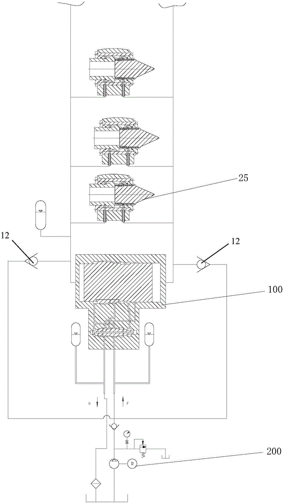
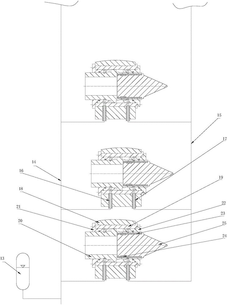
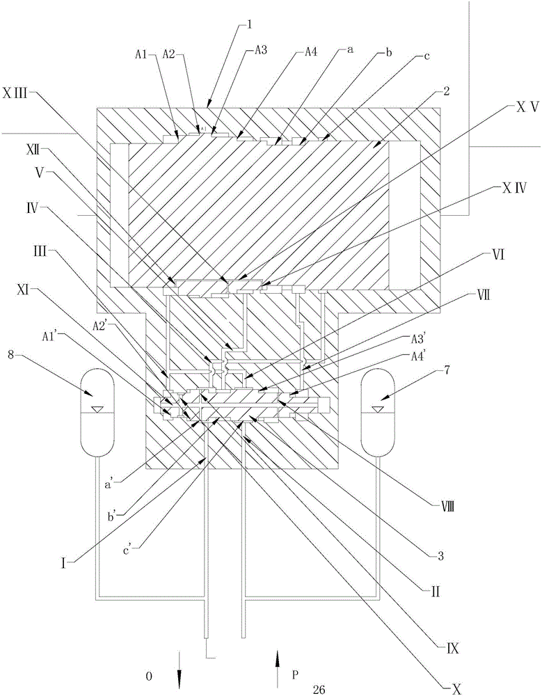
[0026] The specific implementation manner of the present invention will be further described below in conjunction with the accompanying drawings.

[0027] It is easy to understand that, according to the technical solution of the present invention, those skilled in the art can replace various structural modes and implementation modes without changing the essence and spirit of the present invention. Therefore, the following specific embodiments and drawings are only exemplary descriptions of the technical solution of the present invention, and should not be regarded as the entirety of the present invention or as a limitation or restriction on the technical solution of the invention.

[0028] The directional terms such as up, down, left, right, front, back, front, back, top, and bottom that are mentioned or may be mentioned in this specification are defined relative to the structures shown in the drawings, and they are It is a relative concept, so it may change accordingly accord...


PUM


Abstract

The invention discloses a hydraulic control loop for impacting cutting teeth. The hydraulic control loop for the impacting cutting teeth comprises a hydraulic driving unit and an automatic reciprocating unit. The hydraulic driving unit is used for generating hydraulic power which is conveyed to the automatic reciprocating unit, and return liquid of the automatic reciprocating unit returns to the hydraulic driving unit. The automatic reciprocating unit is used for automatically generating repeatedly-alternated low-high pressure, when the high pressure is generated, the automatic reciprocating unit drives the impacting cutting teeth to impact coal and rock masses, and when the low pressure is generated, the automatic reciprocating unit drives the impacting cutting teeth to returned to an original position. The invention further provides an impacting cutting tooth assembly. According to the hydraulic control loop for the impacting cutting teeth and the impacting cutting tooth assembly, abrasion of roller blades and the cutting teeth is reduced, cutting efficiency is improved, cutting power is lowered, the uniform coal drop lumpiness is improved, and the fine coal and dust quantity is reduced.

Description

technical field [0001] The invention relates to the field of mining machinery, in particular to a hydraulic control circuit for an impact pick and an impact pick assembly. Background technique [0002] During the process of breaking coal and rock, the rollers of shearers and roadheaders in coal mines squeeze and rub against the coal and rock mass, and the power consumed in squeezing and friction accounts for about 1 / 3 to 1 / 3 of the cutting power. 2. With the increase of coal hardness, that is, the F value, the wear rate of picks and blades is also accelerated. Severely worn picks and blades increase the cutting resistance, and the working conditions of the cutting drive system tend to deteriorate. If the maintenance of the drum and the replacement of the pick are not timely, it is very easy to cause the rocker arm to be in an overloaded state, causing mechanical failure, and even the gear transmission system of the cutting drive part to fail. In addition, the extrusion and...

Claims


Application Information

Patent Timeline
Patent Type & Authority Applications(China)
IPC IPC(8): E21C35/18F15B11/08F15B1/02
CPCE21C35/18F15B1/02F15B11/08
Inventor 张剑华张云飞王亚军杨增福
Owner CHINA SHENHUA ENERGY CO LTD
Why Eureka
Try Eureka