Electric hair knot opener
An electric and cutter head technology, which is applied in other manufacturing equipment/tools, metal processing, cleaning devices, etc., can solve the problems of non-recyclable, resource waste, etc., and achieve the effect of improving reusable performance, improving work efficiency, and efficient cutting
- Summary
- Abstract
- Description
- Claims
- Application Information
AI Technical Summary
Problems solved by technology
Method used
Image
Examples
no. 1 approach
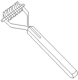
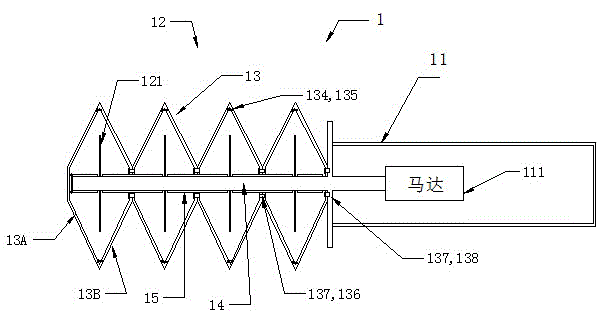
[0054] like figure 2 As shown, the electric knotter 1 of this embodiment includes a handle 11 , a cutter head 12 and a blade cover 13 . The handle 11 is provided with a micro motor 111, and the motor 111 drives the main shaft 14 extending to the cutter head 12 to rotate when electrified. The cutter head 12 is formed by a plurality of blades 121 arranged in parallel at a certain interval on the main shaft 14 , and when the main shaft 14 rotates, each blade 121 rotates together.
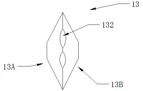
[0055] Wherein, the shape of the blade 121 can be circular, wavy, zigzag, impeller-shaped, hollow-out, or any other shape that is beneficial to cutting hair.
[0056] The cross-sectional shape of the position for installing the blade 121 of the above-mentioned main shaft 14 can be square or other polygons, as long as it is a shape that is convenient for installing the blade 121 and can fix the blade 121 .
[0057] The blade cover 13 covers the entire blade 121 to prevent human hands or animal skin fr...
no. 2 approach
[0066] like Figure 5 , Image 6 As shown, the electric knotter 10 of this embodiment includes: a handle 11 , a cutter head 12 and a blade cover 130 . The material that can be used for the blade cover 130 is the same as that of the blade cover 13 in the first embodiment above.
[0067] The handle 11 is provided with a micro motor 111, and the motor 111 drives the main shaft 14 extending to the cutter head 12 when the power is turned on. The cutter head 12 is formed by a plurality of blades 121 arranged in parallel at a certain interval on the main shaft 14 , and when the main shaft 14 rotates, each blade 121 rotates together. In this embodiment, the cross-sectional shape of the main shaft 14 and the shape that can be adopted by the blade 121 are as described above in the first embodiment.
[0068] Similar to the first embodiment, a plurality of slits 131 cut in a direction perpendicular to the axial direction of the main shaft 14 (towards the main shaft 14 ) is provided on ...
no. 3 approach
[0080] This embodiment is a modified form of the second embodiment.
[0081]Hereinafter, the difference between the present embodiment and the first and second embodiments will be described emphatically.
[0082] In this embodiment, if Figure 10 As shown, one side of the cutter head bottom cover 17B of the electric knotter 100 in the direction parallel to the axial direction of the main shaft 14 is connected with the cutter head bottom cover 17A through a hinge 175, and the cutter head bottom cover of the electric knotter 100 is The edge of the other side of the cover 17B in a direction parallel to the axial direction of the main shaft 14 is fitted into the bit bottom cover 17B.
[0083] In this embodiment, as in the second embodiment, the blade cover 130 may be fixed to the cutter head bottom cover 17B by a fixing mechanism such as a bolt or a screw, or the blade cover 130 and the cutter head bottom cover 17B may be cast or Formed as a whole by injection molding.
[0084]...
PUM
 Abstract
Description
Claims
Application Information
 - R&D
- Intellectual Property
- Life Sciences
- Materials
- Tech Scout
- Unparalleled Data Quality
- Higher Quality Content
- 60% Fewer Hallucinations
Browse by: Latest US Patents, China's latest patents, Technical Efficacy Thesaurus, Application Domain, Technology Topic, Popular Technical Reports.
© 2025 PatSnap. All rights reserved.Legal|Privacy policy|Modern Slavery Act Transparency Statement|Sitemap|About US| Contact US: help@patsnap.com


