Magnetic-field-aided multi-wire-saw cutting machine

A saw cutting machine and magnetic field assisted technology, applied in the field of magnetic field assisted multi-wire saw cutting machine and multi-wire saw cutting machine, can solve the problems of small increase of cutting force, limited magnetic force effect, inconvenient installation and position adjustment of magnetic force source, etc. , to increase the cutting force and avoid wire breakage

Inactive Publication Date: 2014-09-24
王金生 +1
View PDF6 Cites 5 Cited by
  • Summary
  • Abstract
  • Description
  • Claims
  • Application Information

AI Technical Summary

Problems solved by technology

[0004] However, there are still some defects in this wire saw cutting machine: 1. The magnetic source is set on the incoming line side or the outgoing line side of the processing station. The...

Method used


Image

  • Magnetic-field-aided multi-wire-saw cutting machine
  • Magnetic-field-aided multi-wire-saw cutting machine
  • Magnetic-field-aided multi-wire-saw cutting machine

Examples


Embodiment 1

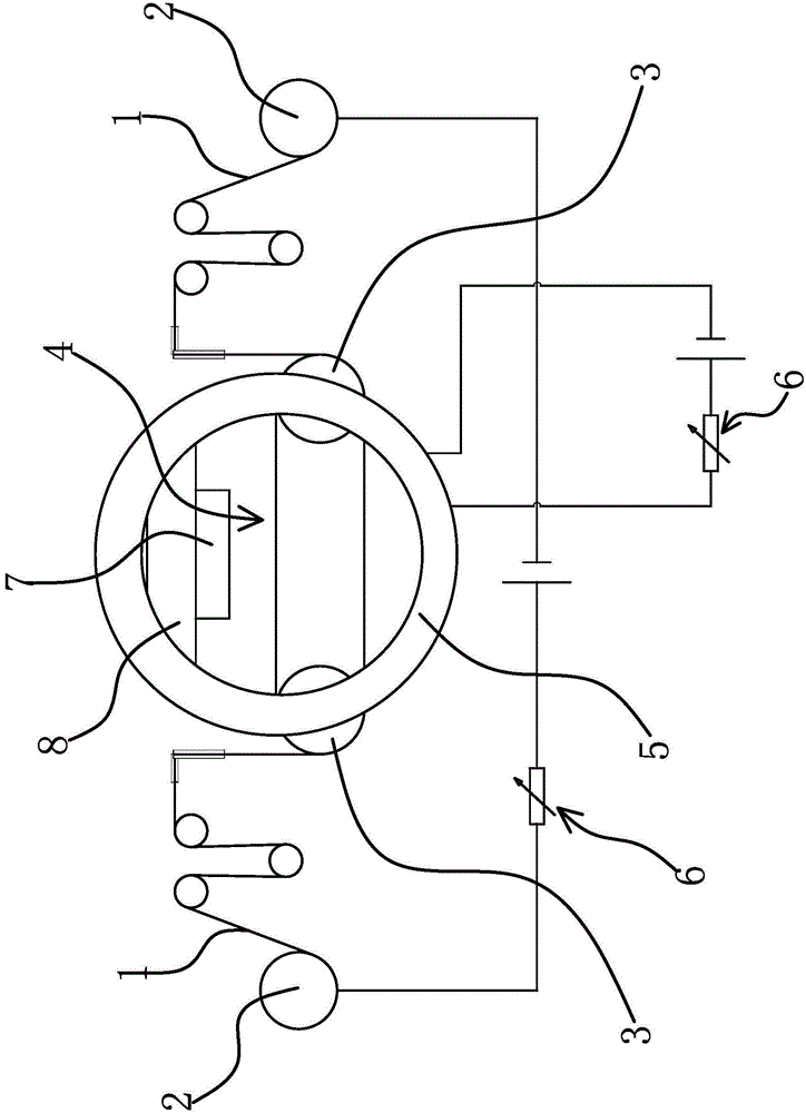
[0030] The multi-wire saw cutting machine includes a wire saw 1, two wire storage wheels 2 and several guide wheels 3. The two ends of the wire saw 1 are respectively wound on the wire storage wheels 2, and the wire storage wheels 2 are rotated so that one end of the wire saw 1 is retracted. The other end of the wire is laid out, and the wire saw 1 is laid on the guide wheel 3 to form a cutting part 4 composed of a plurality of parallel wire saws 1. The wire saw 1 on the cutting part 4 moves in one direction or reciprocates to cut the workpiece 7 to be processed. The multi-wire saw cutting machine assisted by the magnetic field also includes a power supply device and a magnetic field generating device.

[0031] Specifically, as figure 1 As shown, the two ends of the wire saw 1 are respectively connected to the positive and negative poles of the power supply device, so that the current direction on the cutting part 4 is the same. The magnetic field generating device is located...

Embodiment 2

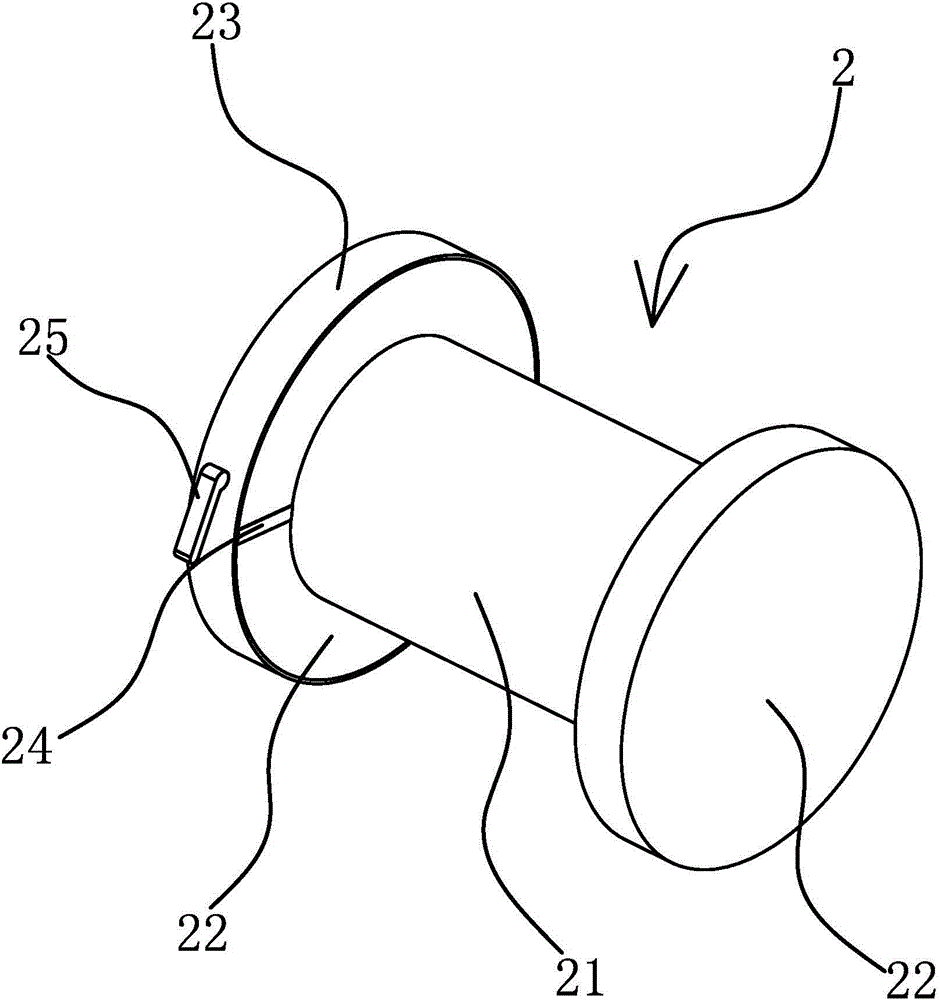
[0036] The technical solution in this embodiment is basically the same as the technical solution in Embodiment 1, the difference is that, as Figure 4 As shown, in this embodiment, the storage part 21 of the storage wheel 2 also has a conductive strip 24, and the conductive strip 24 directly passes the current to the wire saw 1 located in the storage part 21, so that the contact in the circuit is better.

Embodiment 3

[0038] The technical solution in this embodiment is basically the same as the technical solution in Embodiment 1, the difference is that in this embodiment, the center lines of the two coils 5 are located on the same straight line, and the positions of the coils 5 are fixed. The magnitude of the current controls the strength of the magnetic field. As a preferred solution, the radius and the number of turns of the two coils 5 are the same, and the distance between the two coils 5 is equal to half the diameter of the coils 5. In the multi-wire saw cutting machine, affected by the width of the cutting part 4, the distance between the two coils 5 The distance is difficult to get very close, the magnetic field strength of the cutting part 4 is small, and the current in the wire saw 1 cannot reach a high value. Therefore, in the process of actually using magnetic field-assisted cutting, the effect is often not ideal. It is found through repeated tests that when the two coils 5 meet ...


PUM


Abstract

The invention provides a magnetic-field-aided multi-wire-saw cutting machine, and belongs to the technical field of wire saw cutting. The problem that an existing multi-wire-saw cutting machine is low in cutting efficiency is solved. The magnetic-field-aided multi-wire-saw cutting machine comprises a wire saw, two wire storage wheels and a plurality of guide wheels, wherein two ends of the wire saw are respectively wound on the wire storage wheels; when the wire storage wheels rotate, one end of the wire is taken up, and the other end of the wire saw is paid off; the wire saw is laid on the guide wheels to form a cutting part which consists of multiple parallel wire saws and is used for cutting a to-be-processed workpiece; the two ends of the wire saw are respectively and electrically connected with a power supply device; currents on the cutting part have the same direction; two sides of the cutting part are provided with a magnetic field generating device which can generate a magnetic field to enable the direction of ampere force applied to the parallel wire saws to be opposite to the feeding direction of the to-be-processed workpiece. According to the magnetic-field-aided multi-wire-saw cutting machine, when the wire saw is powered on, the magnetic field generating device generates the magnetic field; the powered-on parallel wire saws on the cutting part is subjected to the ampere force, so that cutting force for cutting the to-be-processed workpiece of the parallel wire saws is enhanced.

Description

technical field [0001] The invention belongs to the technical field of wire saw cutting, and relates to a multi-wire saw cutting machine, in particular to a magnetic field-assisted multi-wire saw cutting machine. Background technique [0002] The wire saw cutting technology refers to passing a copper-plated steel wire around the tensioning device, and then winding back and forth around the guide wheel with grooves to form a row of wire nets and maintain a tension of 20N to 30N. During the wire saw cutting process, the wire saw moves relative to the workpiece to be processed at a certain speed under the drive of the guide wheel, and the workpiece to be processed makes a feed motion and exerts force on the wire saw to make the wire saw cut the workpiece to be processed, and the wire saw is relatively In the horizontal position, there is a certain opening angle. The effect of the wire saw cutting the workpiece to be processed is not only related to the performance of the abras...

Claims


Application Information

Patent Timeline
IPC IPC(8): B28D5/04H01F7/00
Inventor 王金生李子法汪超
Owner 王金生
Why Eureka
Try Eureka