A force-limiting double-release lock tank device

A dual-release and tank-locking technology, which is used in transportation and packaging, elevators, lifting equipment in mines, etc., can solve problems such as the existence of hidden safety hazards of sliding ropes, inconvenient installation and maintenance, and the up and down movement of cages. The phenomenon of tank stop impact, easy installation and maintenance, rapid and stable effect of cage

Active Publication Date: 2016-03-30
XUZHOU SUNSHINE SCI TECH CO LTD
View PDF9 Cites 0 Cited by
  • Summary
  • Abstract
  • Description
  • Claims
  • Application Information

AI Technical Summary

Problems solved by technology

[0005] 1. Due to the short buffer stroke of the tank locking device and the influence of factors such as the elastic elongation of the steel wire rope, the impact phenomenon of tank stopping is common, and safety hazards such as loose ropes and slipping ropes sometimes exist;
[0006] 2. When the mine car enters and leaves the cage, it will produce an impact, which will make the cage shake from side to side, and the elastic elongation of the steel wire rope caused by the load change will cause the cage to move up and down, and the mine car will easily fall off the road;
[0007] 3. A separate receiving device solves the problem of stable container receiving in general deep mines, but it cannot meet the requirements for safe and stable tanks in deep vertical shaft lifting. It is necessary to add a tank stabilizing device to make the overall structure complex, which is not easy to install and maintain

Method used


Image

  • A force-limiting double-release lock tank device
  • A force-limiting double-release lock tank device
  • A force-limiting double-release lock tank device

Examples


Embodiment Construction

[0029] The present invention will be further described below in conjunction with the accompanying drawings.

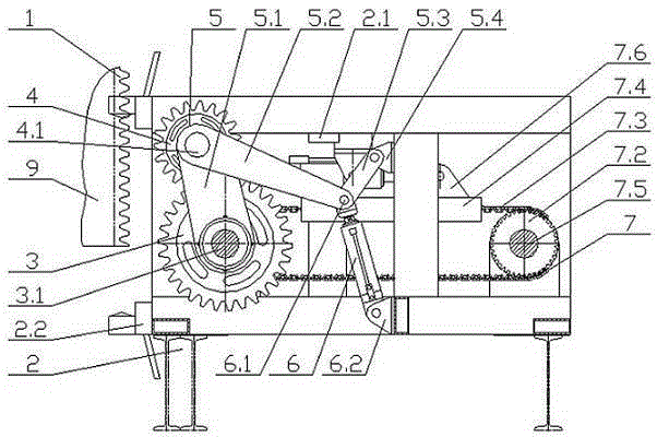
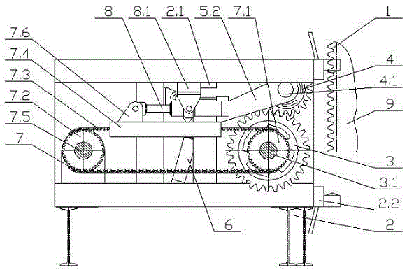
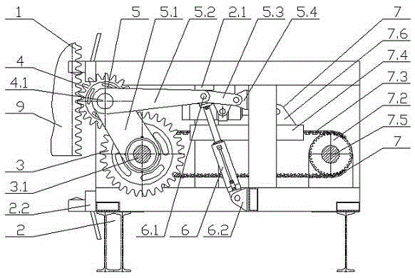
[0030] Such as figure 1 , figure 2 As shown, the force-limiting double-release lock tank device includes a rack 1, a support frame 2, a transmission gear 3, a lock gear 4, a support linkage 5, a drive cylinder 6, a sprocket transmission mechanism 7 and a lock cylinder 8.

[0031] The rack 1 is fixed on the cage 9.

[0032] The supporting frame 2 is a frame structure.

[0033] The transmission gear 3 is erected inside the support frame 2 through the transmission shaft 3.1, the locking gear 4 is erected inside the support frame 2 through the gear shaft 4.1, the locking gear 4 is connected with the transmission gear 3 through the support linkage mechanism 5, and the transmission gear 3 and the locking gear 4 meshing, the locking gear 4 meshes with the rack 1, the transmission gear 3 can be installed with the transmission shaft 3.1 through a key connection, and the tra...


PUM


Abstract

The invention discloses a force limiting double releasing cage locking device which comprises a gear rack (1), a supporting frame (2), a transmission gear (3), a locking gear (4), a supporting link mechanism (5), a driving oil cylinder (6), a chain wheel transmission mechanism (7) and a locking oil cylinder (8), wherein the gear rack is fixedly connected with a cage (9); the supporting frame adopts a frame structure, and is arranged corresponding to the gear rack; the transmission gear, the locking gear, the supporting link mechanism, the driving oil cylinder, the chain wheel transmission mechanism and the locking oil cylinder are all arranged at the inner part of the supporting frame. The cage locking device adopts the manner of meshing the gear and the gear rack, switches linear displacement into circumferential displacement, and then switches circumferential displacement into linear displacement through chain transmission, thereby shortening the cushioning stroke and then ensuring that the locking oil cylinder has enough cushioning stroke; the output cage locking force at the locking gear end can be adjusted through the adjustment of the output pressure of the locking oil cylinder, so that the double functions of locking the cage and stabilizing the cage can be realized; the structure is relatively simple, and the mounting and maintenance are convenient.

Description

technical field [0001] The invention relates to a tank lock device, in particular to a force-limiting double-release tank lock device, which is generally used at the wellhead, bottom and intermediate levels of mine vertical shafts. The inner rail of the cage is aligned with the outer rail of the roadway, which has a locking function and can effectively compensate A device for elongating a hoisting rope belongs to the field of coal mine machinery and equipment. Background technique [0002] Cages are necessary equipment for lifting personnel and materials in mine shafts. With the development of my country's coal industry, the hoisting of mine auxiliary shafts gradually develops in the direction of deep and heavy, that is, the lifting depth exceeds 800 meters and the total lifting weight exceeds 80 tons, when the cage is loaded and unloaded, because the cage is pulled by the wire rope, and the wire rope is a magnetic body, if the mine is deep and the wire rope is long, the load...

Claims


Application Information

Patent Timeline
Patent Type & Authority Patents(China)
IPC IPC(8): B66B5/28B66B17/04
Inventor 于拥军
Owner XUZHOU SUNSHINE SCI TECH CO LTD
Why Eureka
Try Eureka