Side-pass optical fiber processing device and method of use thereof

A processing device, side-pass technology, applied in the field of side-pass optical fiber processing devices, can solve problems such as difficult air discharge, unfavorable development of enterprises, and influence on the efficiency and quality of D2 processing, achieving simple structure, low cost, Good large-scale production and use effect

Active Publication Date: 2017-02-01
成都中住光纤有限公司
View PDF2 Cites 0 Cited by
  • Summary
  • Abstract
  • Description
  • Claims
  • Application Information

AI Technical Summary

Problems solved by technology

[0002] At present, optical fibers need to pass D 2 Treatment is carried out to eliminate the hydroxide absorption peak (commonly known as water peak) near 1380nm, and the usual treatment process is to place the optical fiber wound on the take-up reel in a treatment tank with constant pressure for a certain period of time. Contains D 2 , using D 2 The free movement of molecules gradually permeates around the optical fiber, and combines with the Si-O-broken bond in the optical fiber to form a stable Si-O-D. The bonding energy of the deuterium-oxygen bond is greater than that of the hydrogen-oxygen bond, so that the hydroxyl radical can be avoided formation, so that the hydroxide absorption peak near 1380nm (commonly known as the water peak) can be eliminated. This process usually takes more than 20 hours. The biggest disadvantage of such treatment is that under constant pressure, it is difficult to remove the remaining in the gap between the optical fibers. air out, let D 2 effectively wraps around the fiber
And with the improvement of optical fiber production technology, more and more optical fibers are wound by the take-up reel, which seriously affects the D 2 The efficiency and quality of processing are not conducive to the development of the industry and the growth of enterprises

Method used


Image

  • Side-pass optical fiber processing device and method of use thereof
  • Side-pass optical fiber processing device and method of use thereof
  • Side-pass optical fiber processing device and method of use thereof

Examples


Embodiment 1

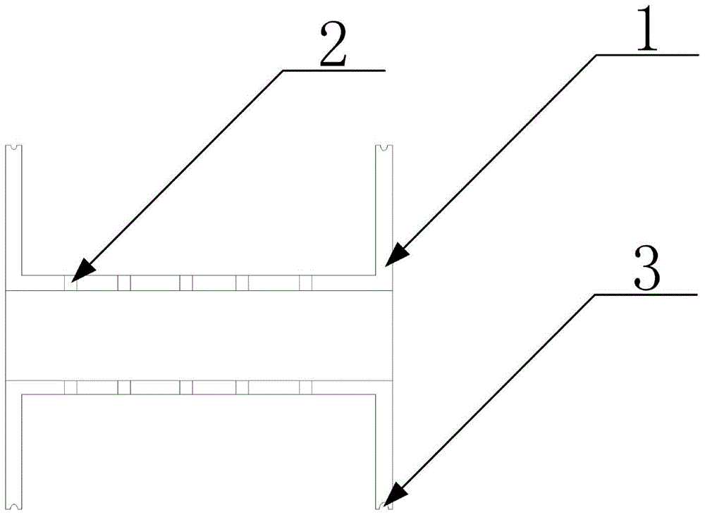
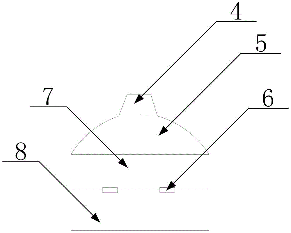
[0023] Such as figure 1 , 2 As shown in , 3, the side-pass optical fiber processing device includes a winding reel main body 1 and an air intake cover, and the winding reel main body 1 and the air intake cover are respectively provided with matching sealing structures.

[0024] A hollow central shaft is provided in the middle of the above-mentioned winding disc main body 1, and a ventilation hole 2 is provided on the central shaft, and an air outlet is also provided at the end of the central shaft. There are two air outlets, which are respectively arranged at two ends of the central axis.

[0025] Preferably, the ventilation holes 4 are arranged in arrays on the shaft wall of the central shaft.

[0026] The sealing structure on the above-mentioned winding disc main body 1 is a card groove 3 provided on its side wall. A sealing ring is also provided.

[0027] The air intake hood includes an air intake interface 4 , an air intake bucket 5 , a fixed wrapping barrel 7 and an o...
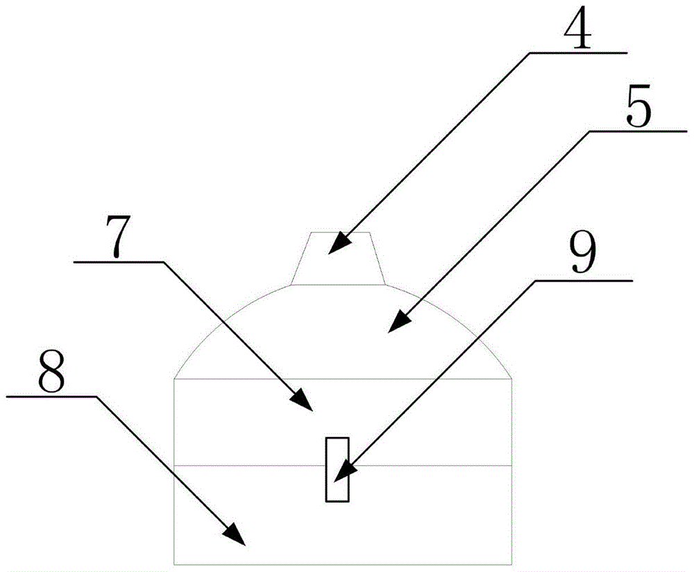
Embodiment 2

[0033] Such as Figure 4 As shown, the only difference between this embodiment and Embodiment 1 is that there is only one air outlet, which is arranged at any end of the central axis.


PUM


Abstract

The invention discloses a side-pass type optical fiber processing device, which comprises a winding reel main body and an air intake cover, and the winding reel main body and the air intake cover are respectively provided with matching sealing structures; the middle part of the winding reel main body is provided with a hollow central shaft , there is also a ventilation hole on the central shaft, and an air outlet is also provided at the end of the central shaft; the sealing structure on the main body of the winding disc is a card slot opened on its side wall, and the number of the card slots is two , and are respectively arranged on both sides of the main body of the winding disc in a ring shape, and a sealing ring is also arranged in the card groove; the air intake cover includes an air intake interface, an air intake bucket, a fixed wrapping bucket and an overturned wrapping barrel. The invention provides a side-through optical fiber processing device, so that the air between the optical fibers can be better discharged, and D2 is better wrapped on the optical fiber while the air is discharged, which greatly improves the processing efficiency and the optical fiber. Quality has promoted the development of the industry and the growth of the enterprise.

Description

technical field [0001] The invention relates to an optical fiber processing device and its use method, in particular to a side-through optical fiber processing device used in the optical fiber manufacturing process. Background technique [0002] At present, optical fibers need to pass D 2 Treatment is carried out to eliminate the hydroxide absorption peak (commonly known as water peak) near 1380nm, and the usual treatment process is to place the optical fiber wound on the take-up reel in a treatment tank with constant pressure for a certain period of time. Contains D 2 , using D 2 The free movement of molecules gradually permeates around the optical fiber, and combines with the Si-O-broken bond in the optical fiber to form a stable Si-O-D. The bonding energy of the deuterium-oxygen bond is greater than that of the hydrogen-oxygen bond, so that the hydroxyl radical can be avoided formation, so that the hydroxide absorption peak near 1380nm (commonly known as the water peak...

Claims


Application Information

Patent Timeline
Patent Type & Authority Patents(China)
IPC IPC(8): C03C25/66
Inventor 张正涛刘文早傅贤德廖度君刘和林向勇曾春洪杨梅
Owner 成都中住光纤有限公司
Why Eureka
Try Eureka