Sound barrier unit plate

A unit board and sound barrier technology, applied in construction, noise absorption devices, etc., can solve the problems of reduced sound absorption effect, reduced sound absorption effect, etc., and achieve the effects of convenient transportation, improved noise reduction effect, and simple assembly.

Inactive Publication Date: 2014-09-24
JIANGSU XINGUANG ENVIRONMENTAL PROTECTION ENG
View PDF9 Cites 8 Cited by
  • Summary
  • Abstract
  • Description
  • Claims
  • Application Information

AI Technical Summary

Problems solved by technology

[0003] However, since the axis of the sound-absorbing plate is perpendicular to the sound-absorbing hole, when the sound wave touches the sound-absorbing material through the sound-absorbing hole on the sound-absorbing plate, some sound waves are still reflected out of the sound-absorbing hole, which reduces the sound-absorbing effect.
The sound wave passes through the sound-abso

Method used


Image

  • Sound barrier unit plate
  • Sound barrier unit plate
  • Sound barrier unit plate

Examples


Example Embodiment

[0020] Example 1:

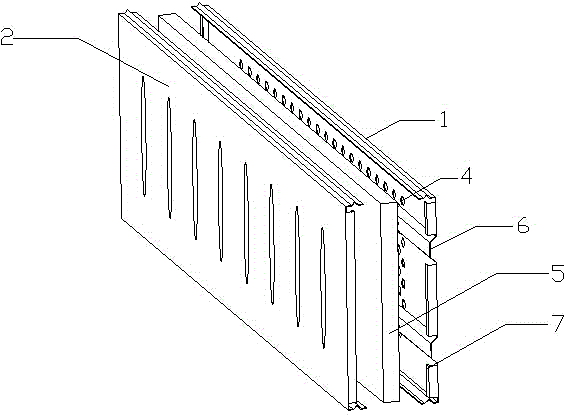
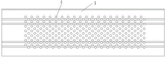
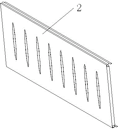
[0021] Such as figure 1 , figure 2 , image 3 , Figure 4 As shown, the sound barrier unit board is composed of a sound-absorbing board 1, a foamed cement board 5, and a sound insulation board 2. The cavity formed between the sound-absorbing board 1 and the sound insulation board 2 is provided with a foamed cement board 5, and the sound-absorbing board 1 has sound-absorbing holes 4, the axial direction of the sound-absorbing holes 4 and the front of the sound-absorbing board are at an angle of 30°, the sound-absorbing holes 4 are regular five-pointed stars, the diameter of the circumscribed circle is 2.6mm, and the opening rate is 70%, the sound insulation board 2 includes a front surface and two side surfaces. The two side surfaces form an angle of 85° with the front surface. The front surface is provided with a convex cone 3. The sound-absorbing panel 1 includes a front surface and two side surfaces. The two side surfaces form an angle of 85 ° with the fro...

Example Embodiment

[0022] Example 2:

[0023] Basically the same as the first embodiment, the difference is that the axial direction of the sound-absorbing hole 4 and the front surface of the sound-absorbing board are at an angle of 45°. The sound-absorbing hole 4 is a regular hexagonal star with a diameter of 5mm. The two sides of the sound insulation board 2 form an angle of 89° with the front, and the two sides of the sound absorption board 1 form an angle of 89° with the front.

Example Embodiment

[0024] Embodiment 3: Basically the same as Embodiment 1, except that the axial direction of the sound-absorbing hole 4 is at an angle of 60° with the front surface of the sound-absorbing board. The sound-absorbing hole 4 is a regular five-pointed star with a diameter of 8mm. , The opening rate is 90%, the two sides of the sound insulation board 2 form an angle of 87° with the front, and the two sides of the sound absorption board 1 form an angle of 87° with the front.


PUM

PropertyMeasurementUnit
Diameteraaaaaaaaaa
Diameteraaaaaaaaaa
Diameteraaaaaaaaaa

Abstract

The invention discloses a sound barrier unit plate, which belongs to the field of environment protection. The sound barrier unit plate consists of a sound absorption plate, a sound absorption material and a sound isolation plate, wherein the sound absorption material is arranged in a cavity formed between the sound absorption plate and the sound isolation plate. Sound waves enter a foamed cement plate sound absorption material through sound absorption holes formed in the sound absorption plate, a great number of tiny communicated pores are formed inside the sound absorption material, the sound waves can go deep into the material along the pores to generate friction effects with the material, and the sound energy is converted into heat energy. The sound waves passing through the foamed cement plate sound absorption material collide with the surface of a sound isolation material, and are then reflected to the foamed cement plate sound absorption material to generate secondary friction effects with the material, and the sound energy is converted into the heat energy for a second time, so the sound isolation effect is achieved.

Description

technical field [0001] The invention belongs to the field of environmental protection, in particular to a sound barrier unit plate. Background technique [0002] The noise generated during the operation of high-speed railways and road vehicles or equipment will cause relatively large noise pollution to residents, schools and office areas along the road and nearby. At present, sound barriers are mainly used to block the transmission of noise, so as to achieve the purpose of preventing and controlling noise pollution. The traditional sound barrier unit board is composed of a sound-absorbing board, a sound-absorbing material, and a sound-insulating board. The sound-absorbing material is set in the cavity formed between the sound-absorbing board and the sound-insulating board, and the sound waves pass through the sound-absorbing holes on the sound-absorbing board. Entering the sound-absorbing material, the sound wave can go deep into the material along the pores of the sound-ab...

Claims


Application Information

Patent Timeline
IPC IPC(8): E01F8/00
Inventor 冯雷高琍玲马成良蒋立新王卫东宣君许晶晶
Owner JIANGSU XINGUANG ENVIRONMENTAL PROTECTION ENG
Why Eureka
Try Eureka