Multi-barrel cyclone desander and multi-barrel cyclone desanding method

A technology of desander and drum rotation, which is applied in the field of oilfield surface engineering produced fluid treatment, which can solve the problems of inability to adjust the treatment capacity, reduce the desanding efficiency, and unreasonable structure, so as to increase the number of high-efficiency working points and improve the desanding efficiency , the effect of improving adaptability

Active Publication Date: 2014-09-24
PETROCHINA CO LTD +2
View PDF6 Cites 1 Cited by
  • Summary
  • Abstract
  • Description
  • Claims
  • Application Information

AI Technical Summary

Problems solved by technology

[0005] (1) Unreasonable structure
The sand swirled down by the swirl tube settles into the closed static shell without flow by gravity, causing some small-sized mud and sand to fail to enter the shell at the bottom of the swirl tube due to the continuous swirl of the fluid inside the swirl tube. In the body, it enters the liquid outlet instead, reducing the sand removal efficiency
[0006] (2) The processing capacity cannot be adjusted, and the adaptability is poor
The processing capacity of the oilfield production fluid treatment station is designed according to the maximum predicted liquid production in the next 10-15 years. In the initial stage of at least 3-5 years when the new production fluid treatment station is put into operation, the actual liquid production of the oilfield will be low Due to the designed processing capacity of the treatment station, the current single-chamber chamber desander cannot adjust the processing capacity, causing the cyclone to work in the low-efficiency area with low processing load

Method used


Image

  • Multi-barrel cyclone desander and multi-barrel cyclone desanding method
  • Multi-barrel cyclone desander and multi-barrel cyclone desanding method
  • Multi-barrel cyclone desander and multi-barrel cyclone desanding method

Examples


Embodiment Construction

[0040] In order to make the purpose, technical solutions and advantages of the embodiments of the present invention clearer, the technical solutions in the embodiments of the present invention will be clearly and completely described below in conjunction with the drawings in the embodiments of the present invention. Obviously, the described embodiments It is a part of embodiments of the present invention, but not all embodiments.

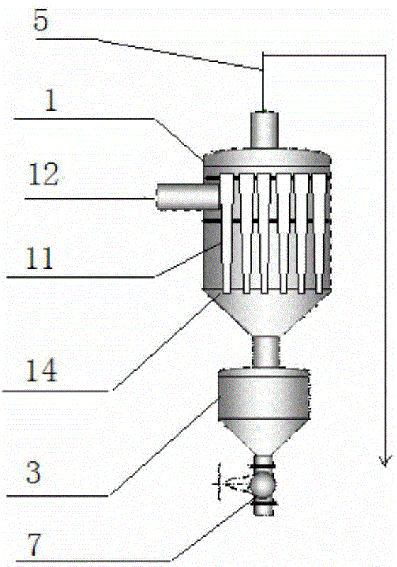
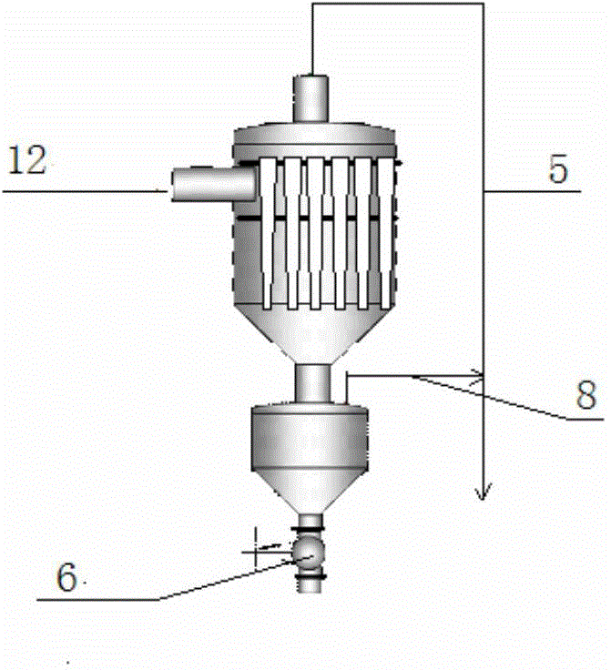
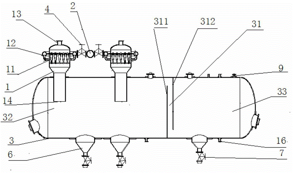
[0041] Such as Figure 1B As shown in the schematic diagram, by setting a drainage pipe on the top of the existing cyclone desander shell (i.e. sand collection cabin), a drainage and sand dragging mechanism is constructed to completely change the bottom flow of the current cyclone desander. The structure of the closed non-flow shell at the mouth realizes high-efficiency sand removal; the parallel connection of multiple cylinders realizes adjustable processing capacity and increases the number of efficient work points.

[0042] Based on the above pr...


PUM


Abstract

The invention discloses a multi-barrel cyclone desander and relates to the technical field of oil field surface engineering produced fluid treatment. The multi-barrel cyclone desander comprises multiple bundled cyclone pipe barrels, a feed liquid collecting pipe, a shell, a liquid inlet valve, a liquid outlet pipe, a sand discharge bag, a sand discharge valve and a drainage pipe, wherein the multiple bundled cyclone pipe barrels are connected in parallel, and the right top of the shell is provided with a drainage port communicated with the drainage pipe, so that fluid flow is established in the shell. The invention also discloses a multi-barrel cyclone desanding method used for realizing solid-liquid cyclone separation of a cyclone pipe, and drainage, sand dragging, sedimentation and static liquid separation of the shell. The invention provides perfect desanding equipment and the perfect desanding method. The multi-barrel cyclone desander and the multi-barrel cyclone desanding method have the advantages of high desanding efficiency and adjustable treatment capacity, and can be used for increasing efficient operating points and improving the adaptability of the desander to oil field liquid-producing capacity spontaneous changes.

Description

technical field [0001] The invention belongs to the technical field of oil field surface engineering production fluid treatment, and in particular relates to a multi-tube cyclone desander and a desander method. Background technique [0002] Oilfield production fluids contain sediment, which is an impurity in petroleum products and needs to be removed. In particular, production fluids containing polymers, ternary composite media, and heavy oil production fluids have high sand content, which makes purification treatment of production fluids very difficult, pipelines and treatment equipment are silted, and project investment and operating costs are greatly reduced. rise. Since the fine particles in the liquid mud sand produced in such oilfields account for a large proportion and are difficult to remove, how to achieve efficient sand removal in oilfield produced liquids has become a worldwide problem. [0003] At present, oilfields at home and abroad adopt cyclone sand removal...

Claims


Application Information

Patent Timeline
IPC IPC(8): E21B43/34
Inventor 宋承毅张昌兴王庆伟孙占华肖义群
Owner PETROCHINA CO LTD
Why Eureka
Try Eureka