Coupled inductor

A technology of coupled inductors and magnetic cores, applied in the field of coupled inductors, can solve the problems of large inductor width, increase coil cost, reduce inductor power density, etc., and achieve the effect of high-performance coupled inductors

Active Publication Date: 2016-08-24
HUAWEI DIGITAL POWER TECH CO LTD
View PDF12 Cites 0 Cited by
  • Summary
  • Abstract
  • Description
  • Claims
  • Application Information

AI Technical Summary

Problems solved by technology

[0004] However, the coil 13 needs to be wound on the first frame core 11 and the second frame core 12 at the same time, which increases the cost of the coil. Moreover, the second frame core 12 needs to extend to both sides, resulting in a larger inductance width. large, reducing the inductor power density

Method used


Image

  • Coupled inductor
  • Coupled inductor
  • Coupled inductor

Examples


Embodiment Construction

[0026] The following will clearly and completely describe the technical solutions in the embodiments of the present invention with reference to the accompanying drawings in the embodiments of the present invention. Obviously, the described embodiments are only some, not all, embodiments of the present invention. Based on the embodiments of the present invention, all other embodiments obtained by persons of ordinary skill in the art without creative efforts fall within the protection scope of the present invention.

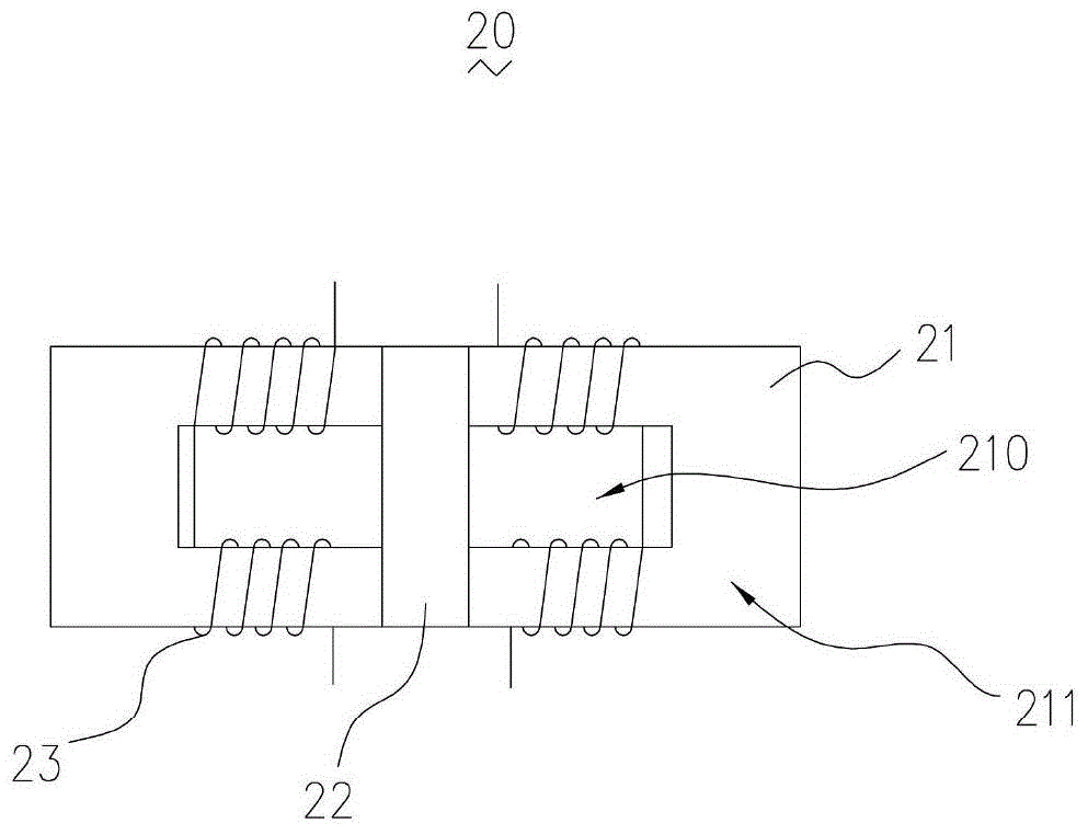
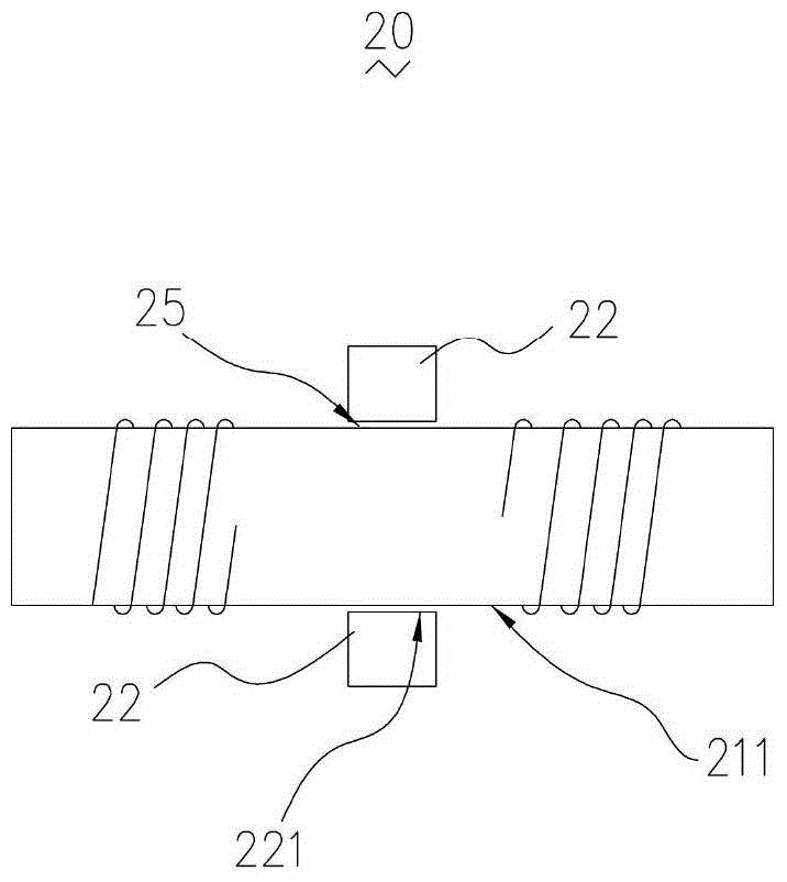
[0027] see Figure 2 to Figure 4 The first embodiment of the present invention provides a coupled inductor 20, the coupled inductor 20 includes a first magnetic core 21 and a first group of coils and a second group of coils wound on the first magnetic core 21, the first The magnetic core 21 is a frame magnetic core, a group of opposite sides of the frame magnetic core includes a first side and a second side, and the first side includes a first part, a second part a...


PUM


Abstract

The present invention provides a coupled inductor, the coupled inductor includes a first magnetic core and a first group of coils and a second group of coils wound on the first magnetic core, the first magnetic core is a frame magnetic core, A set of opposite sides of the frame magnetic core includes a first side and a second side, the first side includes a first part, a second part and a third part, the second side also includes three parts, the first side The second part of the side is located between the first part and the third part, the distribution of the three parts of the second side is consistent with the first side, and the first group of coils surrounds the first part of the first side and the second side The first part of the side is wound, the second group of coils is wound around the third part of the first side and the third part of the second side, the coupled inductor also includes a second magnetic core, so The second magnetic core is arranged between the two groups of coils, and an air gap is formed between the second magnetic core and the second part of the first side or the second part of the second side.

Description

technical field [0001] The invention relates to the field of power electronics, in particular to a coupled inductor. Background technique [0002] In recent years, coupled inductors have been widely used in the field of power electronics technology. The use of coupled inductors in power electronic converters can not only significantly improve the dynamic performance and efficiency of the power electronic converter and increase the output switching frequency, but also reduce the output ripple current and greatly reduce the size and cost of the power electronic converter. [0003] like figure 1 As shown, an existing coupled inductor 10 includes a first frame core 11, two second frame cores 12 and two coils 13, the first frame core 11 and each second frame core 12 respectively include two opposite magnetic pillars and two opposite magnetic yokes, wherein: two second frame body cores 12 are respectively located on both sides of the first frame body core 11, and each second fra...

Claims


Application Information

Patent Timeline
Patent Type & Authority Patents(China)
IPC IPC(8): H01F38/14H01F27/24H01F27/30
Inventor 叶飞石磊傅电波
Owner HUAWEI DIGITAL POWER TECH CO LTD
Why Eureka
Try Eureka