Contact of vacuum arc extinguishing chamber

A vacuum interrupter, arc contact technology, applied in high-voltage air circuit breakers, electrical components, electrical switches, etc., can solve the problems of high breakdown field strength, large arc, contact surface burnout, etc., and achieve good breaking capacity , the effect of low cost

Inactive Publication Date: 2014-09-24
王永法
View PDF5 Cites 6 Cited by
  • Summary
  • Abstract
  • Description
  • Claims
  • Application Information

AI Technical Summary

Problems solved by technology

[0003] The vacuum interrupter is mainly composed of airtight insulating shell, shielding system, dynamic and static contacts, bellows, conductive rods and other parts. Since the dynamic and static contacts of the vacuum interrupter are the parts that generate and extinguish the arc, the protection of the contact The material and structure requirements are relatively high. In the existing technology, most of the materials with high pressure resistance and electric corrosion resistance such as copper-chromium alloy are used to make the moving contact and the static contact. The moving contact and the static contact pass through Spherical or plane surface contact, this contact has the following disadvantages: first, when the switch is closed, the static contact and the moving contact are in contact, and the arc may generate an arc at any position where the static contact and the moving contact contact , and under the action of the arc, the metal at the position where the arc is generated is easy to evaporate, and the contact end surface of the moving contact and the static contact is easy to be uneven, thereby increasing the contact resistance between the moving contact and the static contact, and affecting the vacuum arc extinguishing Chamber breaking capacity
Second, because the moving contact and the static contact are in surface contact, the effective area is large when the gate is opened, and the breakdown field strength is high, which is easy to cause a large arc and cause burning of the contact surface

Method used


Image

  • Contact of vacuum arc extinguishing chamber
  • Contact of vacuum arc extinguishing chamber
  • Contact of vacuum arc extinguishing chamber

Examples


Embodiment Construction

[0014] Below in conjunction with accompanying drawing and specific embodiment the present invention will be described in further detail:

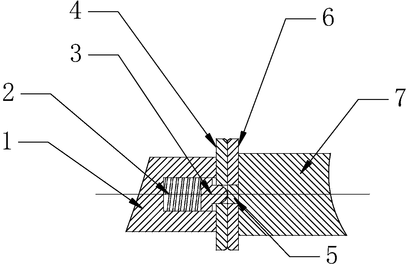
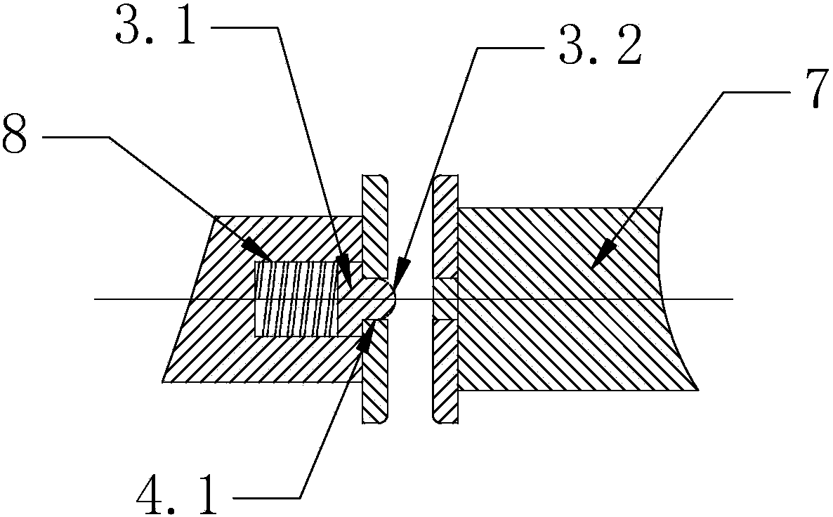
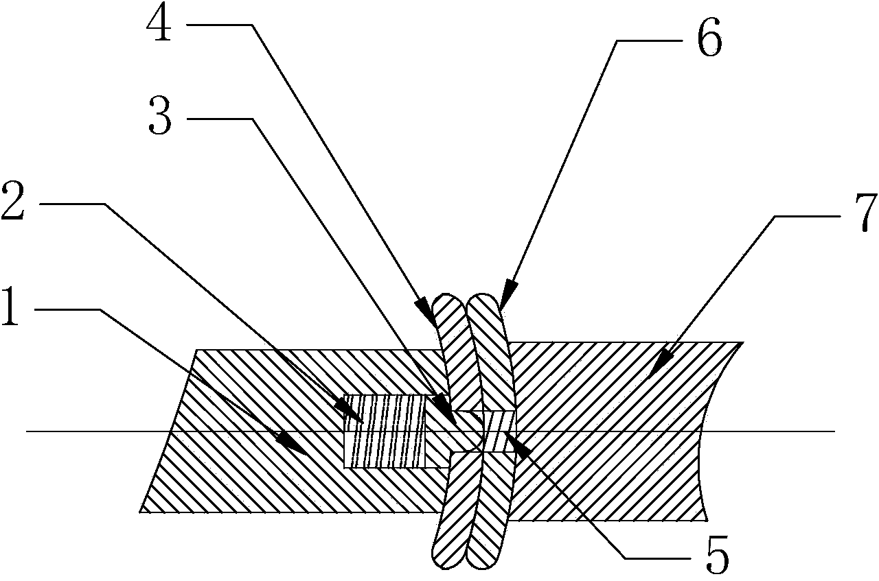
[0015] Such as figure 1 , figure 2 As shown, the embodiment provides a contact of a vacuum interrupter, which includes a first contact 4 and a second contact 6, the first contact 4 is connected to a first conductive rod 1, the first contact The second contact 6 is connected with a second conductive rod 7, and the end surface of the first contact 4 is provided with an arcing contact 3 that protrudes from the end surface of the first contact 4 when the gate is opened. Connected to the first conductive rod 1 through the spring 2, the end surface of the second contact 6 is provided with an auxiliary contact 5 for cooperating with the arc contact 3 to generate an arc.

[0016] In this embodiment, the end surfaces of the first contact 4 and the second contact 6 are circular flat plates, the first contact 4 is a moving contact, and the second c...


PUM


Abstract

The invention provides a contact of a vacuum arc extinguishing chamber. The contact comprises a first contact and a second contact. The first contact is connected with a first conducting rod, and the second contact is connected with a second conducting rod. An arc ignition contact is arranged on and protrudes out of an end surface of the first contact. The arc ignition contact is connected inside the first conducting rod by a spring. An auxiliary contact is arranged on an end surface of the second contact and is used to cooperate with the arc ignition contact to generate an arc. The invention provides the contact reducing the breakdown field strength, controlling the arcing point, improving the interrupting capability of the vacuum arc extinguishing chamber, and having a low cost.

Description

technical field [0001] The invention relates to the technical field of electric switches, in particular to a contact of a vacuum interrupter. Background technique [0002] The vacuum interrupter, also known as the vacuum switch tube, is the core component of the medium and high voltage power switch. Its main function is to quickly extinguish the arc and suppress the current after the medium and high voltage circuit is cut off through the excellent insulation of the vacuum in the tube, so as to avoid accidents and accidents. It is mainly used in the transmission and distribution control system of electric power. [0003] The vacuum interrupter is mainly composed of airtight insulating shell, shielding system, dynamic and static contacts, bellows, conductive rods and other parts. Since the dynamic and static contacts of the vacuum interrupter are the parts that generate and extinguish the arc, the protection of the contact The material and structure requirements are relativel...

Claims


Application Information

Patent Timeline
Patent Type & Authority Applications(China)
IPC IPC(8): H01H33/664
Inventor 王永法朱维娜
Owner 王永法
Why Eureka
Try Eureka