Explosion-proof wiring device

An explosion-proof wiring and wiring cavity technology, applied in the direction of connection, conductive connection, electrical components, etc., can solve the problems of easy sealing failure, easy loosening of cable joints, etc.

Inactive Publication Date: 2014-09-24
SICHUAN TIANWEI ELECTRONICS
View PDF5 Cites 4 Cited by
  • Summary
  • Abstract
  • Description
  • Claims
  • Application Information

AI Technical Summary

Problems solved by technology

[0004] Aiming at the problems in the prior art that the seal at the joint between the junction box and the cable is easy to fail, and the cable joints in the junction box are easy to loosen under the action of the tension of the cables at both ends, the present invention provides an explosion-proof wiring device

Method used


Image

  • Explosion-proof wiring device
  • Explosion-proof wiring device
  • Explosion-proof wiring device

Examples


Embodiment 1

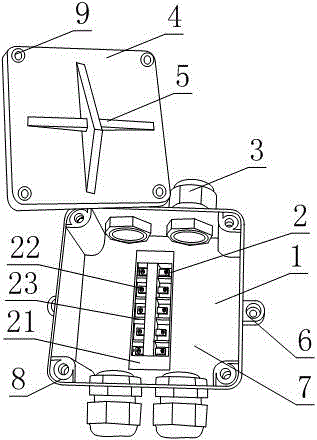
[0029] Such as Figure 1 to Figure 5 , an explosion-proof wiring device, including a groove-shaped base 1 and an upper cover 4 connected with the base 1 by bolts or screws, a wiring cavity 7 is formed between the base 1 and the upper cover 4, and the side of the base 1 is also At least one threading pipe 3 is fixed, and the wiring part 2 is also arranged in the wiring cavity 7;

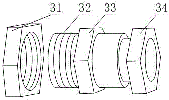
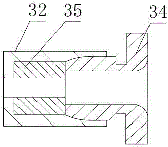
[0030] The threading pipe 3 includes a lead tube 32 fixed on the base 1, a through hole with a different diameter is provided on the axis of the lead tube 32, an internal thread is provided at one end of the through hole with a different diameter, and a thread is embedded in the through hole with a different diameter. Gasket 35, the internally threaded hole is provided with a compression nut 34 that is threadedly connected with it, one end of the compression nut 34 is in contact with one end of the gasket 35, and the other end of the gasket 35 is positioned relative to the lead barrel 32 The relation...

Embodiment 2

[0034] The present embodiment is further limited on the basis of embodiment 1, as Figure 1 to Figure 5, because the base 1 and the upper cover 4 are mostly made of plastic materials in the prior art, no matter for safety considerations or material saving considerations. Failure, the base 1 is fixed with a plurality of threaded seats 8 for connecting the base 1 and the upper cover 4 with bolts or screws, and the threaded seats 8 are all internal threaded metal sleeves embedded in the base 1. In this embodiment The threaded seat 8 is a copper sleeve provided with an internal thread, and the fixed connection between the base 1 and the upper cover 4 is realized through the screw holes 9 provided on the upper cover 4 corresponding to the inner threaded seat 8 one-to-one.

Embodiment 3

[0036] The present embodiment is further limited on the basis of embodiment 1, as Figure 1 to Figure 5 , in order to ensure the sealing performance between the base 1 and the upper cover 4 , a sealing ring 10 is also provided between the connecting end faces of the base 1 and the upper cover 4 .


PUM


Abstract

The invention discloses an explosion-proof wiring device comprising a base and an upper cover. A wiring cavity is formed between the base and the upper cover. At least one threading pipe is fixed on the side of the base. The wiring cavity is internally provided with a wiring part. Each threading pipe includes a lead cylinder, a different-diameter through hole is arranged in the axis of the lead cylinder, one end of the different-diameter through hole is provided with internal threads, a sealing pad is embedded in the different-diameter through hole, a compression nut in threaded connection with an internal threaded hole is arranged in the internal threaded hole, the lead cylinder is further provided with external threads, a locking bolt is arranged on the external threads, and a bulge is arranged on the lead cylinder. The wiring part comprises a wiring part seat and at least one wiring plate, and each wiring plate includes a conducting plate on which at least two threading openings and at least one compression bolt are arranged. The explosion-proof wiring device has a simple structure, is applicable to explosion-proof connection of cables within a certain range of wire diameter, and has the characteristics of good sealing and flameproof performances, high cable wiring head connection speed and high wire connector connection stability.

Description

technical field [0001] The invention relates to a wire and cable protection device, in particular to an explosion-proof wiring device. Background technique [0002] The underground environment of coal mines is special, and there are flammable gases and dusts. Once the above-mentioned gases and dusts reach the explosion limit and encounter any electric sparks, it is very easy to cause serious production safety accidents. Therefore, all kinds of communication, monitoring, instrumentation and automation in mines It is particularly important for system equipment such as explosion-proof function. [0003] Underground coal mines have many lighting facilities and power equipment, and junction boxes are indispensable equipment in the process of zero-time long line and cable wiring. In the prior art, the seal at the joint between the junction box and the cables is prone to failure, and the cable joints in the junction box are easily loosened under the action of the tension of the ca...

Claims


Application Information

Patent Timeline
Patent Type & Authority Applications(China)
IPC IPC(8): H01R9/00H01R9/22
Inventor 李吉杨海燕杨德志奂建东
Owner SICHUAN TIANWEI ELECTRONICS
Why Eureka
Try Eureka