
Device and method for discharging products, particularly product containers such as bottles

A technology of unloader and product, which is applied in the field of devices for container products such as bottles, which can solve the problems of high unloading speed, entering pause time, etc.

Active Publication Date: 2014-09-24
KRONES AG
View PDF8 Cites 3 Cited by
  • Summary
  • Abstract
  • Description
  • Claims
  • Application Information

AI Technical Summary

Problems solved by technology

However, there is a delay time between different unloading operations on the device because the carriage needs to be moved back to the initial position first
In order to reduce this delay time, relatively high unloading speeds in a direction perpendicular to the direction of motion of the products on the conveyor may be required, which can cause problems especially for light-weight or fragile products
It also has the disadvantage that even with only one defective unloading section, the entire installation is forced into a standstill for necessary repairs

Method used


Image

  • Device and method for discharging products, particularly product containers such as bottles
  • Device and method for discharging products, particularly product containers such as bottles
  • Device and method for discharging products, particularly product containers such as bottles

Examples


Embodiment Construction

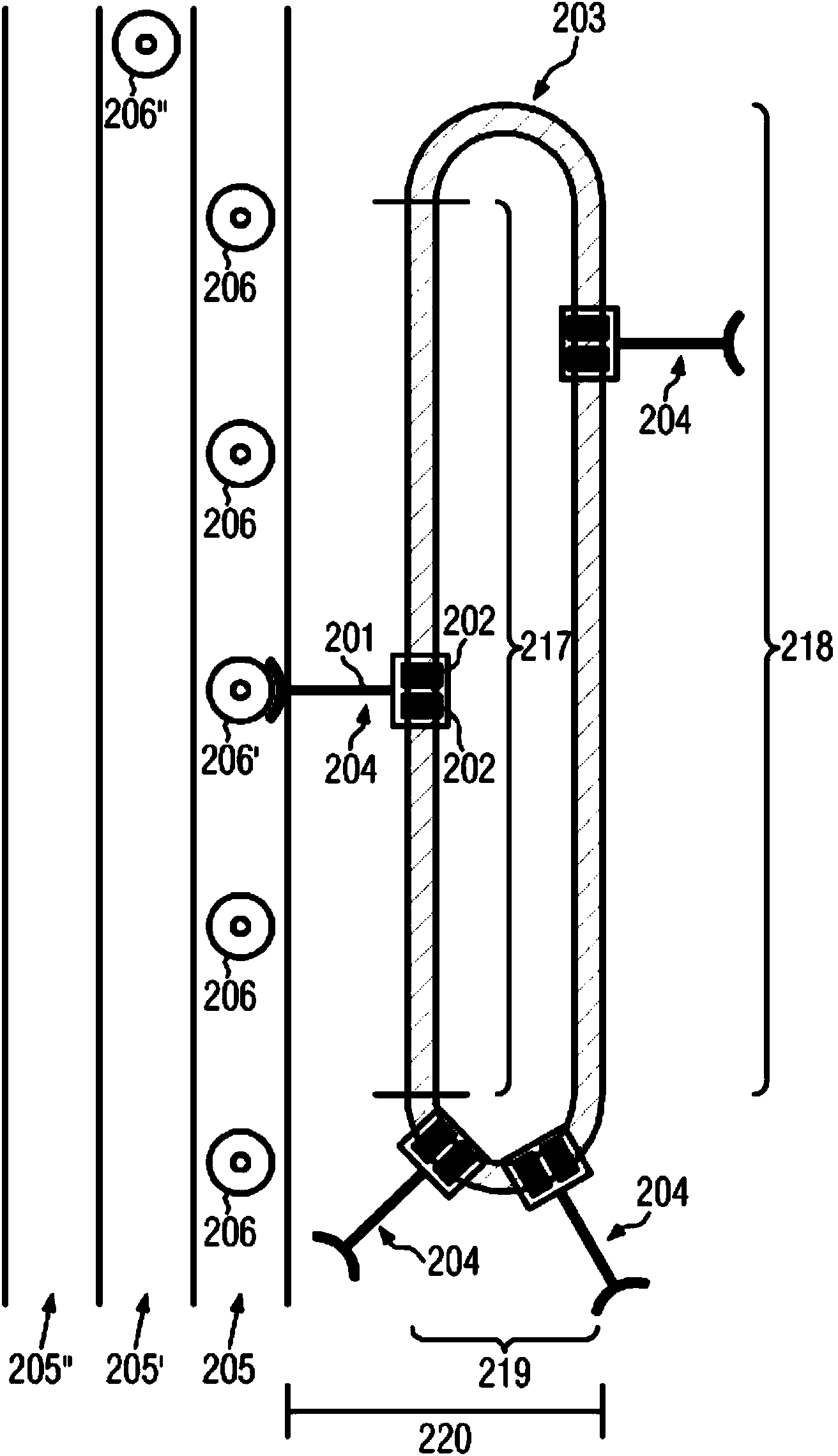
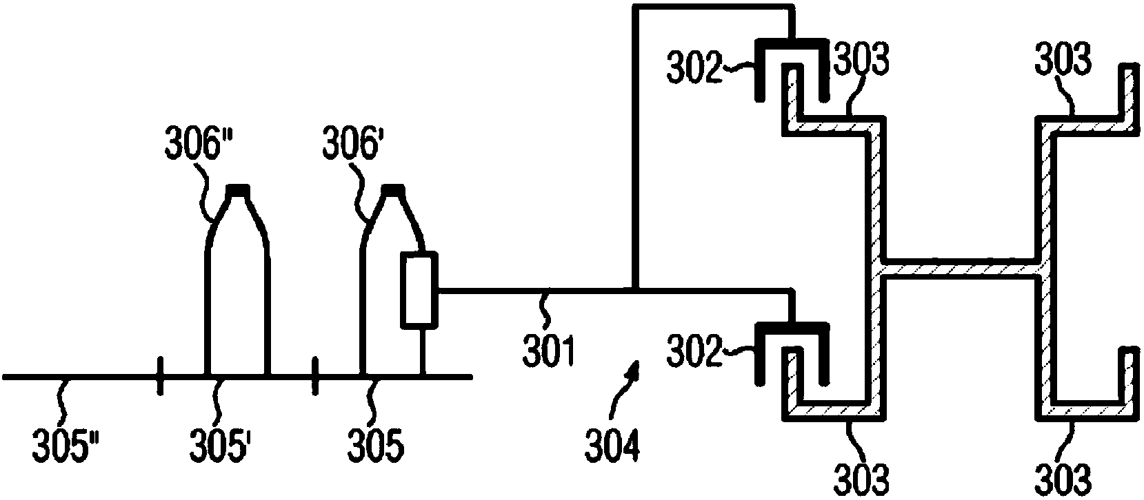
[0030] The unloading of products, in particular container products such as bottles, is done by means of an unloading device having one or more unloading sections.

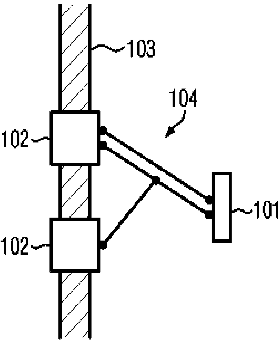
[0031] figure 1 The unloading section 104 on the corresponding guide rail 103 is schematically illustrated. The connection between the unloading section 104 and the guide rail 103 is realized by two carriages 102 connected to the guide rail 103 . In addition to said carriage 102, the unloading section 104 comprises an unloader 101 enabling product unloading by physical contact. By changing the relative distance of the carriages 102 to each other, the products to be unloaded can be unloaded by changing the offset of the unloader 101 . A change in the relative position of the carriage 102 on the rail 103 can be produced by changing the relative speed of the carriage. Here, the speed of one or both carriages 102 is changed for a limited time, so that the resulting speed difference between the two carriages within a...


PUM


Abstract

The invention relates to a device and a corresponding method for discharging products, particularly product containers such as bottles from a transport path by means of one or more discharge segments (104), wherein the or each discharge segment (104) comprises a carriage (102) and a discharger (101), and said discharger (101) can effect the discharge of the product by a deflection, wherein the or each discharge segment (104) comprises a second carriage, wherein each of the two carriages is mounted on a guide and the discharger (101) and the carriages (102) are mechanically connected to one another such that the relative distance of the carriages from one another determines the deflection of the discharger (101).

Description

technical field [0001] The invention relates to a device for unloading products, in particular container products such as bottles, from a transport path. Background technique [0002] There are various unloading systems in the prior art. [0003] For example, patent DE3130308 C2 already discloses a device for unloading rejects from a conveyor belt. In this device, the unloading operation is performed by an unloading element driven by a linear motor. The unloading elements are arranged on guide rails leading to the conveyor belt and can be collected in the form of cassettes. To unload the rejects, one of the unloading elements is guided on the guide rail towards the product, which is then pushed by the element by physical contact to a conveyor belt extending parallel to the conveyor belt. The individual unloading elements are rigid; the push onto the conveyor belt is done only by the inclined position of the guide rails. [0004] The device has the advantage that the unlo...

Claims


Application Information

Patent Timeline
Patent Type & Authority Applications(China)
IPC IPC(8): B65G47/82B65G47/84
CPCB65G47/841B65G54/02B65G47/71B65G47/845B65G47/34
Inventor 康拉德·森马瑞克·约瑟夫威茨
Owner KRONES AG
Learn More