Mechanical coolant pump

A coolant pump, mechanical technology, applied in engine cooling, coolant flow control, mechanical equipment, etc., can solve problems such as high actuation power

Active Publication Date: 2014-09-24
PIERBURG PUMP TECH
View PDF6 Cites 4 Cited by
  • Summary
  • Abstract
  • Description
  • Claims
  • Application Information

AI Technical Summary

Problems solved by technology

However, high actuation power is required to ensure full functionality at all rotational speeds

Method used


Image

  • Mechanical coolant pump
  • Mechanical coolant pump
  • Mechanical coolant pump

Examples


Embodiment Construction

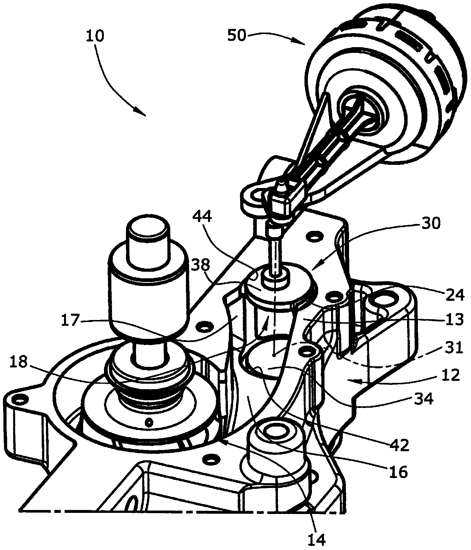
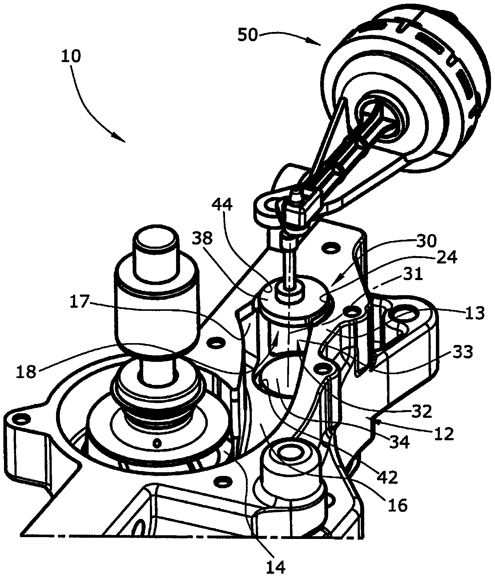
[0022] Figures 1 to 6 A mechanical coolant pump 10 for circulating coolant for an internal combustion engine is shown. The coolant pump 10 can be mounted directly to the engine block of the internal combustion engine. The coolant pump 10 is provided with a drive wheel (not shown) which can be driven by a drive belt directly driven by the internal combustion engine. The rotational speed of the coolant pump 10 is proportional to the rotational speed of the internal combustion engine.

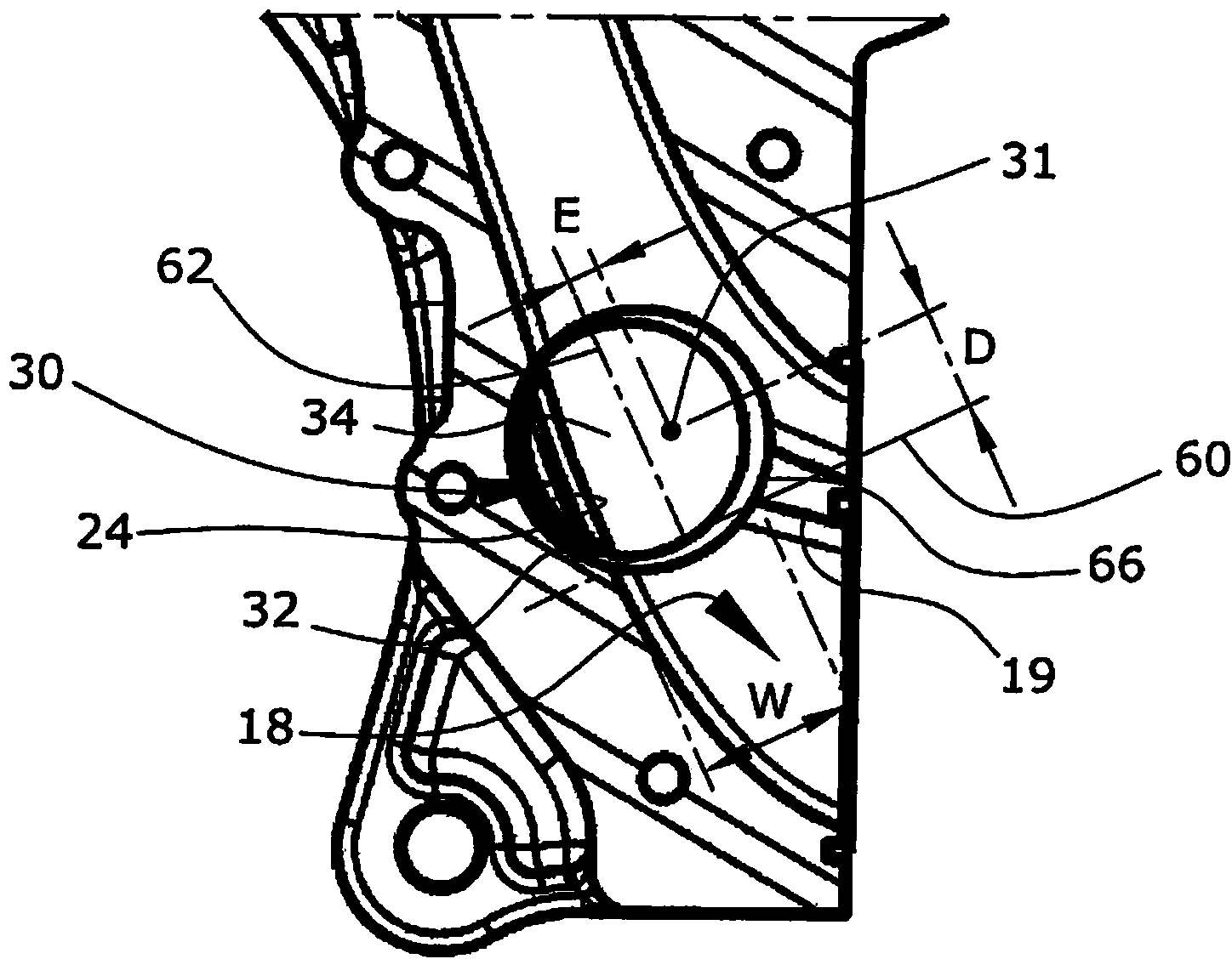
[0023] The coolant pump 10 is provided with a pump housing 12 which houses an impeller pump wheel 14 which radially pumps liquid coolant introduced in the axial direction into an outlet volute 16 . The outlet volute 16 is defined by the volute 13 which is part of the pump casing 12 . The axial coolant pump inlet is provided on the bottom side of the coolant pump 10, as figure 1 and 2 shown in .

[0024] The outlet volute 16 comprises a first outlet channel 18 and a second outlet channel 17 ...


PUM


Abstract

The invention refers to a mechanical coolant pump ( 10) for an internal combustion engine. The pump 10 comprises an impeller pump wheel ( 14) pumping the liquid coolant incoming in axial direction radially into an outlet volute ( 16), a pump housing (12) including a outlet volute housing (13) defining the outlet volute (16) including a first outlet channel (18), and an outlet valve arrangement in the route of the first outlet channel ( 18). The outlet valve arrangement comprises valve flap (30) being pivotable between an open position and a closed position to leave open or close a valve opening (19) of the outlet channel (18). The valve opening ( 19) is defined and surrounded by a valve seat (64) defining a valve seat plane (60) and a symmetry plane (62) in the middle of and rectangular to the valve seat plane (60). A valve flap (30) is provided with a flap seat (66) corresponding to the valve seat (64). The valve flap (30) is rotatable around a pivot axis (31) which is in parallel to the symmetry plane (62) and is located with a lateral eccentricity (E) from the symmetry plane (62), whereby the lateral eccentricity (E) is between 1/20 and 1/1 of the pivot axis' distance (D) to the valve seat plane (60).

Description

technical field [0001] The invention relates to a mechanical coolant pump for an internal combustion engine. Mechanical coolant pumps are driven by the internal combustion engine, for example by using a drive belt to drive the drive wheels of the pump, so that the rotational speed of the coolant pump is proportional to the rotational speed of the internal combustion engine. When the internal combustion engine is cold, only a minimum amount of coolant flow is required. Therefore, mechanical coolant pumps are equipped with an outlet valve arrangement for controlling the flow of coolant leaving the coolant pump. As long as the internal combustion engine is cold, the outlet valve is closed so that the circulation of lubricant is reduced, minimized or completely stopped, thereby shortening the warm-up phase of the internal combustion engine. Background technique [0002] WO 2011 / 101019 A1 discloses an impeller coolant pump with an outlet valve arrangement at the root of the out...

Claims


Application Information

Patent Timeline
Patent Type & Authority Applications(China)
IPC IPC(8): F01P5/10F01P7/16F04D29/46F04D15/00
CPCF01P11/00F01P7/16F04D1/00F04D15/0005F04D1/04F01P5/10F04D15/0022
Inventor A.福尼尔P.乔治斯G.希蒙
Owner PIERBURG PUMP TECH
Why Eureka
Try Eureka